Scott,
Have we found another area to disagree?
If I take two gain stages and apply global feedback, and compare that to the same two stages each with local feedback for the same gain and compare that to two stages with partial local feedback and overall global feedback to the same gain, you support that all of these will have the same final distortion spectra?
In B.P.s article he allows as his error may be a complex function and then shows it as a single term added in at the end of the network. That is true but it is more enlightening if there is an error term added in at each stage. That way you see the e^2 or ^3....
ES
Given that intermediate stages may have different signal levels in these three different scenarios it is unlikely that the outcome will be the same. The exception will be if all the distortion arises in the later stages in the second opamp - this will see the same signal level for a given output level.simon7000 said:If I take two gain stages and apply global feedback, and compare that to the same two stages each with local feedback for the same gain and compare that to two stages with partial local feedback and overall global feedback to the same gain, you support that all of these will have the same final distortion spectra?
Given that intermediate stages may have different signal levels in these three different scenarios it is unlikely that the outcome will be the same. The exception will be if all the distortion arises in the later stages in the second opamp - this will see the same signal level for a given output level.
Lets assume that none of the stages clip.
PMA, I think that it was 5V pp. for the 741 graph.
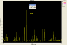
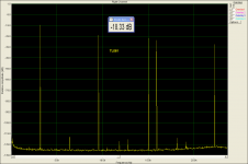
Could not find the 741. So I took OP177 (0.3V/us) and TL061 (3V/us). Test signal is 3.3Vpp. The test signal is bandlimited at 24kHz.
Attachments
Last edited:
Let me check around I might be able to propose a simple experiment with the AD844.
I am all ears.

Statements of measurable fact have been made concerning these circuit techniques that can be proven as measurable phenomena to be wrong.
Can you give more details ?
If you want to criticize some of GlenK and sny08's designs as being over engineered that's fine. If you say that they are no different than the Goldmund cloners (I don't read those threads) I disagree.
I am curious about those designs: what are they remarkable for ?
If I take two gain stages and apply global feedback, and compare that to the same two stages each with local feedback for the same gain and compare that to two stages with partial local feedback and overall global feedback to the same gain...
I think it would be very helpful in these discussions if people could specify
whether they are referring to "local loop" or degeneration or what mix
when they talk about local feedback.
Degeneration and loop feedback are not the same thing, one of the issues
I have with Bruno's article, as he has made statements that imply that
they are.
you really shouldn't believe (your own) marketing on this
no one teaching EE, issuing degrees does
as I've pointed out: http://www.diyaudio.com/forums/pass-labs/132491-distortion-negative-feedback-31.html#post2491343
no one teaching EE, issuing degrees does
I think it would be very helpful in these discussions if people could specify
whether they are referring to "local loop" or degeneration or what mix
when they talk about local feedback.
Degeneration and loop feedback are not the same thing, one of the issues
I have with Bruno's article, as he has made statements that imply that
they are.
as I've pointed out: http://www.diyaudio.com/forums/pass-labs/132491-distortion-negative-feedback-31.html#post2491343
Last edited:
Degeneration and loop feedback are not the same thing, one of the issues
I have with Bruno's article, as he has made statements that imply that
they are.
Please do explain what the difference is. It would be really nice to get this seemingly simple point cleared up once and for all
I think it would be very helpful in these discussions if people could specify
whether they are referring to "local loop" or degeneration or what mix
when they talk about local feedback.
Degeneration and loop feedback are not the same thing, one of the issues
I have with Bruno's article, as he has made statements that imply that
they are.
For simplicity I mean a complete amplifier (I.E. op amp) with a gain setting feedback resistor. I do not mean using techniques such as an emitter resistor to decrease the gain of a stage.
One of the issues I was aiming at is that with a classic op-amp configuration with a single pole roll off the gain at DC will approach infinity. That means the input signal at DC must approach zero. Any LF noise above the maximum output voltage divided by the very high gain must induce clipping. (Of course bandwidth limiting must be used with a super gain configuration, but there still should be 1/F clipping. That means clipping recovery is an important issue.)
The second issue was approached by DF96 in that the linearity is affected by signal level. This is well know and goes by many names and other than acknowledging it exists, it is not an area I want to go to as it creates more heat than light.
A third issue is that distortion introduced by one stage will be both multiplied and in some cases cancelled by a following stage. ( This was side stepped in B.P.'s article by using a single error term and assigning all errors to it, not showing how it compounds.) This will create lower levels of high order harmonics and may cancel some even order ones. A major issue is what level of harmonic is important. I think I demonstrated to at least a few that the 9th needs to be at least 80 db down and quite possibly much more.
Another issue is that mathematical prediction and modelling must be followed by experimental confirmation. Doing this often shows missed issues.
A possible conclusion is that we may be able to measure, predict and confirm the distortion spectra of a multistage amplifier, but it is a personal issue to assign value to the results.
I apologize in advance for trying to make this as clear as I can, usually most folks don't understand my points and so I don't have to waste time on arguments.
Last edited:
Could not find the 741. So I took OP177 (0.3V/us) and TL061 (3V/us). Test signal is 3.3Vpp. The test signal is bandlimited at 24kHz.
Pavel,
When I expand the 741 plot to full size and use my calipers, the basic spacing is 15mm.
When I set the calipers for 7.5mm I can account for pretty much all of the spectra above the -119 grid line, but a lot of the stuff below doesn't line up. Is this noise? Is it repeatable?
ES
I apologize in advance for trying to make this as clear as I can, usually most folks don't understand my points and so I don't have to waste time on arguments.
Thanks for the clarity. I have an interest in some of these details, and I
like to think about the issues with them in mind.
no one teaching EE, issuing degrees does
Surely you are not appealing to authority.
My point is that degeneration, as in inserting resistance in series with
the Source pin of the Mosfet is not the same thing as feeding the Drain
signal back to the Gate. They have some similar effects, and a couple
of obvious differences, but my main interest is that they do not exhibit
the same distortion characteristic, especially in the degree to which they
introduce higher order harmonics.
when the authority comes from over 70 years of practice by engineers, technologists creating our modern world I don't think such an appeal counts as a flawed argument/weak rhetorical technique
millions of man hours have been spent developing, studying, teaching, applying feedback theory
enough time has passed that even if you believe theories of scientific thought can only be overturned/reformulated by the retirement/death of the older generation by now feedback theory has had time for several complete turnovers
that the "Classical" Bode sensitivity analysis view of feedback theory is still being presented in modern textbooks gives a fair indication of its practical utility, agreement among practitioners on its useful formulation as a theory
claiming Hansen says so IS a weak appeal to authority
sampling output current with a source series R is well understood as a good way to control the drain current - Crss, Cgs currents are tiny fractions of a percent of the drain or source currents at audio frequencies for most audio power fet applications such that Id is within 0.1% of Is is entirely practical at 20 kHz
as my linked comment mentioned there is the whole series/shunt formalism available for classifying some “non-obvious” negative feedback arrangements
http://users.ece.gatech.edu/mleach/ece3050/notes/feedback/fdbkamps.pdf
care to point to a circuit that shows the difference between degeneration, negative feedback that you're asserting?
care to point to a circuit that shows the difference between degeneration, negative feedback that you're asserting?
A cathode/emitter/source degenerated device has the intrinsic properties of a new device with new characteristics, and cannot be distinguished if treated as a black box from a (hypothetical) device "born" with the new characteristics. There is no need to invoke a causal chain to describe the new characteristics.
Other "feedback" has a causal chain and an interaction of discrete devices and loops. Put another way, feedback has entropy and an arrow of time.
"That is my theory and what it is too!" - Anne Elk
Thanks,
Chris
blinded by the glory...
“I don’t know what you mean by ‘glory,’ ” Alice said.
Humpty Dumpty smiled contemptuously. “Of course you don’t—till I tell you. I meant ‘there’s a nice knock-down argument for you!’ ”
“But ‘glory’ doesn’t mean ‘a nice knock-down argument’,” Alice objected.
“When I use a word,” Humpty Dumpty said, in rather a scornful tone, “it means just what I choose it to mean—neither more nor less.”
“The question is,” said Alice, “whether you can make words mean so many different things.”
“The question is,” said Humpty Dumpty, “which is to be master that’s all.”
Alice was too much puzzled to say anything, so after a minute Humpty Dumpty began again. “They’ve a temper, some of them—particularly verbs, they’re the proudest—adjectives you can do anything with, but not verbs—however, I can manage the whole lot! Impenetrability! That’s what I say!”
Last edited:
Pavel,
When I expand the 741 plot to full size and use my calipers, the basic spacing is 15mm.
When I set the calipers for 7.5mm I can account for pretty much all of the spectra above the -119 grid line, but a lot of the stuff below doesn't line up. Is this noise? Is it repeatable?
ES
Simon,
firstly, the slow opamp is OP177, as I could not find the uA741.
The measurement is repeatable, and number and amplitude of the "stuff" depends on input signal amplitude, i.e. on the degree how much we approach (or exceed) the slew rate limit of the opamp under test. Here, the opamp slew rate is 0.1V/us - 0.3V/us (according to datasheet) and input signal seems to have slew rate about 0.15V/us. The more we approach the opamp slew rate limit, the more "stuff" we get.
Opamp's voltage gain is +1.
Regards,
Last edited:
- Status
- Not open for further replies.
- Home
- Member Areas
- The Lounge
- John Curl's Blowtorch preamplifier part II