For those of you using Holm, what are you using for impedance measurement and crossover simulation? I've previously used Speaker Workshop for everything, but since I got Holm working a while ago on my laptop, I'm planning to use it in the future for response measurements. I'm sure I could import that to Speaker Workshop and use SW to measure impedance as well, but I was wondering if people had any better (free) options?
Last edited:
SBA - Thanks for your input. It's much appreciated, as the more help I can get the quicker I can make good clean measurements that maybe useful to me and other folks in the future who maybe using the same horns,drivers,etc... that I'm using now.I admit I have been struggling with this quite a bit.As I have had to depend on others for most of my learning.All in a relatively short amount of time.I almost threw in the towel several times as I didn't want to be a victim of this !!! I have gotten a tremendous amount of support from Pano.Without his knowledge,and support none of this would have been possible for me that much I can assure you !! So Thank You Mr.Panomaniac !") I'm going to start a new thread as this one is getting quite slow with all the attach.and replies.
I'm going to start a new thread as this one is getting quite slow with all the attach.and replies.
"Measurement Basics using Holm Impulse" Thanks to all for the support for this enthusiastic audio geek
Here's the Link: http://www.diyaudio.com/forums/mult...nt-basics-using-holm-impulse.html#post2375011
I'm going to start a new thread as this one is getting quite slow with all the attach.and replies."Measurement Basics using Holm Impulse" Thanks to all for the support for this enthusiastic audio geek
Here's the Link: http://www.diyaudio.com/forums/mult...nt-basics-using-holm-impulse.html#post2375011
Last edited:
"Measurement Basics using Holm Impulse"
This is a carry over thread from Holm Impulse measurements in practice.As the thread was getting quite big,and was loading slowly on my computer and thought it was a good idea to start on a clean slate.As I have been having a lot of issues getting this measurement gear all setup correctly.
I would like to Thank Again all that have replied to my questions and requests for Help !! I appreciate your kind/gracious support.I'm very new to the measuring aspect of audio Unfortunately! I find it quite fun when all is working the way it was supposed to.
SBA, OK now WRT changing the start frequency before a sweep.I have tried that but it seems if I start anywhere other than 20 Hz Holm doesn't seem to like it.With measurements that are off the wall strange !!
This is a carry over thread from Holm Impulse measurements in practice.As the thread was getting quite big,and was loading slowly on my computer and thought it was a good idea to start on a clean slate.As I have been having a lot of issues getting this measurement gear all setup correctly.
I would like to Thank Again all that have replied to my questions and requests for Help !! I appreciate your kind/gracious support.I'm very new to the measuring aspect of audio Unfortunately!
I find it quite fun when all is working the way it was supposed to.SBA, OK now WRT changing the start frequency before a sweep.I have tried that but it seems if I start anywhere other than 20 Hz Holm doesn't seem to like it.With measurements that are off the wall strange !!
Last edited:
Have you taken a look at this link? Great basics on setting up the measurements in HI. More info than in the original .pdf doc found at the HI site. Great for HI noobies.
HOW TO: Measure using HOLM and ARTA - AVS Forum
HOW TO: Measure using HOLM and ARTA - AVS Forum
try ARTA (?)
No not yet.I have REW on my computer but that is a lot more complicated for me.I need to just get started measuring for a bit then those should come much more easily.
Have you taken a look at this link? Great basics on setting up the measurements in HI. More info than in the original .pdf doc found at the HI site. Great for HI noobies.
HOW TO: Measure using HOLM and ARTA - AVS Forum
Not yet but I will.I will check this out tonight after dinner Thanks Again !!
Very Informative thread there Thanks Again for posting it.
HOW TO: Measure using HOLM and ARTA - AVS Forum=
HOW TO: Measure using HOLM and ARTA - AVS Forum=
Does anyone have any thoughts on the question I asked in post 400, please
I presume that you are using the MiniDsp as a X-over with two amps?
If so, the different looking dips and humps between the passive And Dsp
curves is (maybe) due to the fact that the passive filter has a 180 degree
phase shift at X-over frequency. Try change the polairty of the mid in the
passive setup!
- - My "uninstall", didn't remove this folder ( this is "strange" to a Mac guy ) .
- Once I sent the orphaned folder to the recycling bin, I was able to successfully run the programs' installer ( & download the latest version onto my computer ) .
Yes, unistallers on Windoze leave a lot to be desired - because they often leave a lot behind! Constant house cleaning is needed.
Try Revo Uninstaller it is Free !! It is very thorough.
I presume that you are using the MiniDsp as a X-over with two amps?
If so, the different looking dips and humps between the passive And Dsp
curves is (maybe) due to the fact that the passive filter has a 180 degree
phase shift at X-over frequency. Try change the polairty of the mid in the
passive setup!
The dip shown in the blue line (my SABA mid) is always there, with passive crossover or without any crossover, it also appears when the terminals are inverted.
For the the measurements I did in post 400, I way using one amp, one channel to the mid & one channel to the tweeter. The Red & Green lines are thru the MiniDSP as the crossover & my attempt to eq out the dip.
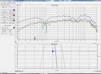
My problem is, HolmImpulse shows the dip, (Green line) at 900hz, only as a dip if you view the gated measurement. If you view the measurement Raw or Smoothed it is a riser.
So which one is correct, Gated, Smoothed/Raw?
The dip shown in the blue line (my SABA mid) is always there, with passive crossover or without any crossover, it also appears when the terminals are inverted.
For the the measurements I did in post 400, I way using one amp, one channel to the mid & one channel to the tweeter. The Red & Green lines are thru the MiniDSP as the crossover & my attempt to eq out the dip.
My problem is, HolmImpulse shows the dip, (Green line) at 900hz, only as a dip if you view the gated measurement. If you view the measurement Raw or Smoothed it is a riser.
So which one is correct, Gated, Smoothed/Raw?
The gated response isn't accurate below 1000 Hz:
The time graph shows that gating stops at about 2 mS, and a correct curve starts at half this time = one millisec which is equal to 1000 Hz.
The most accurate is the raw curve.
What happens if you increase the Gating time to 6 mS?
So which one is correct, Gated, Smoothed/Raw?
It depends on your measurement conditions and what you are trying to see. If you want to see the anechoic response and are measuring in a room, you must use gating and the response will only be valid above a certain frequency (indicated by the gating note) which depends on when you have reflections arriving at the mic. If you are looking at a raw (ungated) response and then smoothing it, of course those two measurements will agree.
The gated response isn't accurate below 1000 Hz:
The time graph shows that gating stops at about 2 mS, and a correct curve starts at half this time = one millisec which is equal to 1000 Hz.
The most accurate is the raw curve.
What happens if you increase the Gating time to 6 mS?
I set the gating to before the first reflection should arrive, I thought that was what you where suppose to do
See below for gating at 6ms, it looks like dipole baffle effect?
Attachments
I think I have it all sorted, after night after night.But would like to Thank all the folks who have replied to requests for help !! Thank You !! 

I'm almost 100% certain that it the (distortion) is from Noise ! And "NOT" from the drivers ! The graphs of the noise are almost identical to the distortion graphs ! If my understanding of this is wrong then someone please correct me,Thanks
John
I'm almost 100% certain that it the (distortion) is from Noise ! And "NOT" from the drivers ! The graphs of the noise are almost identical to the distortion graphs ! If my understanding of this is wrong then someone please correct me,Thanks
John
Last edited:
Time & Phase
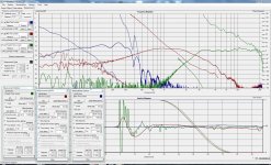
I have tried to take some time measurements of the new speakers, so I could apply a delay for the Mid-Tweeter drivers using the MiniDSP, as expected the Mid & Tweeter appear to be aligned well enough (from my reading) but the bass driver appears to be in the next room
Oh and I have no idea what the phase is trying to tell me so some help there would be greatly appreciated.
David
I have tried to take some time measurements of the new speakers, so I could apply a delay for the Mid-Tweeter drivers using the MiniDSP, as expected the Mid & Tweeter appear to be aligned well enough (from my reading) but the bass driver appears to be in the next room
An externally hosted image should be here but it was not working when we last tested it.
I would say the physical horizontal distance between the MT & bass driver is about 40mm (bass behind MT). Does anyone know how to interpret these measurements.Oh and I have no idea what the phase is trying to tell me so some help there would be greatly appreciated.
David
Attachments
When you connect the output to the input of your soundcard you see the perfect phase what also your speaker shout have. thats easy for comparison.I have tried to take some time measurements of the new speakers, so I could apply a delay for the Mid-Tweeter drivers using the MiniDSP, as expected the Mid & Tweeter appear to be aligned well enough (from my reading) but the bass driver appears to be in the next roomAn externally hosted image should be here but it was not working when we last tested it.I would say the physical horizontal distance between the MT & bass driver is about 40mm (bass behind MT). Does anyone know how to interpret these measurements.
Oh and I have no idea what the phase is trying to tell me so some help there would be greatly appreciated.
David
DQ828: Your phase looks quite right for a 3-way.
Every crossover point with a 4th order filter, makes for a phase shift of 360 degrees. The phase response starts to change approx. 10x below and 10x higher than the attack frequency.
Normally all frequency analysers anticipates 360degrees = 0 degrees, because you have moved to the same point at the next cyclus. Your signal will actually be delayed 1 cycle, which means that the delay in mS will depend on the actual frequency.
Normally the phase shifts are not directly audible, so you should just base your choices for level of delay on each frequency area, on the impulse response. Even that looks nice allready on your graphs. How does it sound?
I hope it makes sense.
- Home
- Design & Build
- Software Tools
- HOLMImpulse: Measurements in practice