ecir38 - Actually the bias resistor in Alex's schematic is R23 (330ohm). This resistor doesn't have to be 3W and it can definitely be variable. However, it's safer to use a fixed resistor in case the wiper lifts by accident. Also, fixed resistor is less detrimental to sonic quality.
I just checked my Goldmund technical notes. If the output MOSFETS are Hitachi 2SK1058/2SJ162 then the bias resistor R23 should be replaced with 220ohm. If the MOSFETS are the old original Hitachi 2SK134/2SJ49, then the resistor will remain as in the schematic, 330ohm. I'm guessing everyone will be using the 2SK1058/2SJ162s as the PCB was designed for them. So, it's important that the resistor R23 is changed to 220ohm.
Also, on the plastic MOSFETS, ferrite beads must be used on the two outer legs.
All of this is per Goldmund service manual.
Relay, have a look.
Link to Factory-Recommended Replacement
Part Number: JTN1AS-TMP-F-DC24V
PANASONIC EW/AROMAT JN1A-TMP-DC24V | Buy JN1ATMPDC24V | JN1A TMP DC24V | Onlinecomponents.com
Mouser has some on order due in December. (note wrong pic)
JTN1AS-TMP-F-DC24V Panasonic Electric Works General Purpose / Industrial Relays
Should we be concerned with any other parts?
Off to RMAF in the morning .
.
Brad
Link to Factory-Recommended Replacement
Part Number: JTN1AS-TMP-F-DC24V
PANASONIC EW/AROMAT JN1A-TMP-DC24V | Buy JN1ATMPDC24V | JN1A TMP DC24V | Onlinecomponents.com
Mouser has some on order due in December. (note wrong pic)
JTN1AS-TMP-F-DC24V Panasonic Electric Works General Purpose / Industrial Relays
Should we be concerned with any other parts?
Off to RMAF in the morning
.Brad
Nagys,
Have you considered you might be making another mistake..................what if Goldmund had preselected and matched their mosfets before assembly, and selected a bias resistor accordingly.(Hint remember Hafler, what did they do?)
What if........................?
For an engineer you are making an awful lot of mistakes in this mad rush to produce a pcb, you probably need to slow down and recheck everything before going to the group buy, this is a bit more complicated than you think, better safe than sorry.
Jam
Goldmund's tag line from 80s to 00s for the Mimesis series of amplifiers have always been that one can replace any transistor without matching it. I have repair numerous Goldmund amplifiers, never once did I match any transistors and never once did the amps not perform anything, but 100% like they should. This is no Hafler.
Hi
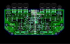
I have a concern about the 10nF decoupling capacitors on the output devices. The idea is to have as short a path as possible at HF between the output devices and the "power ground". Unfortunately the PCB has been laid out so that the "power ground" connection is at the opposite side of the PCB to the output devices.
Fortunately not all is lost as the really important thing is just that there's a short path between the positive rail decoupling caps, the negative rail decoupling caps, and the "earthy" end of the zobel. The path length to the PSU is not so important.
In the pic below, the pink spots show the bits that need to be connected with the shortest possible path lengths. On the left, the green lines show the connections between the positive rail caps and the zobel. On the right, the green lines show the connections between the negative rail caps. So far so good, but...
The long red line shows how the negative rail caps are connected to everything else. Oops, this is not good. Seriously, it doesn't help to put the caps right next to the mosfets if the other end of the caps are connected to a long skinny copper track that snakes around the entire PCB before connecting to anything useful.
As a quick-fix, I'd recommend adding a few wire links between the stuff on the left and the stuff on the right.
If double-sided board is going to be used, it would be really good to have a wide strip of copper across that side of the board as a local power ground plane, with the decoupling caps and zobel soldered directly to it.
Cheers - Godfrey
p.s. All the above is just IHMO. Perhaps someone who understands this stuff better would care to comment?
Attachments
.... yes you are right gotfrey , I know about all you tell as, but when I layout PCB I intended from start to make it single sided to be avaible to all diy people around here .I'm not an proffesional guy , it was only my wish to help this forum .The problem could be solved in an simplier way adding two pices of wires on bottom like in the picture below attached (white line). Next will be double sided.Top side is ground plain ....so no problem.
Regards Alex.
Regards Alex.
Attachments
Last edited:
Nagys,
So you are telling us that this amplifier that uses three pairs of mosfets with no source resistors and no means of adjusting bias will work correctly just like that without matching........I am amazed.
Mosfets can vary quite widely and have to be grouped buy turn on voltage so that they can equally share current when biased on. Not having source resistors makes this more important as you will get into a situation where some devices are doing all the work and others are not. Not having a means of adjusting bias makes this situation worse and calls for matched devices. There is a requirement for lowest distortion at a predetermined bias point as well. I may be wrong here but has Goldmund given you all the required information for replacing output devices on this amp?
The reason I mention Hafler, which you dismissed for no reason, is that they used the same output devices and they produced a device to match moisfets to avoid the above problems, on top of the fact that their amp had a bias adjustment.
You seem to fail to see the problems of the output stage and how to get it working correctly........yet you claim to be an engineer.
I am more amazed.
Jam
Last edited:
Let us give Naggys a break.
His intentions are good and he has been quite patient with all of us criticising this design.
Jam is right though, mosfets vary quite considerably from device to device.
One mosfet at vgs of 400mV might give you 100mA Id and another one might give 20mA Id, and another one might give 200mA Id. That is probably an extreme case but you get what we are saying here hopefully.
I have not measured hitachi mosfets so I don't know what the variation is like.
Last edited:
a look at the datasheet shows that Hitachi knew what the variations were like.I have not measured hitachi mosfets so I don't know what the variation is like.
All the modern equivalents seem to have just as much variation.
Hi thanh,
I did not mean to be too hard on Nagys but I had to point potential problems that members might face when building this amp.
I have seen quite a wide variation of Vgs for the above devices and had to match them when I worked on Haflers. Hafler had good documentation on matching requirements with their little box.
I also had taken a Golmund apart years ago and noticed that their output devices seem to have been matched. I also at the time was on the search for the Holy Grail of amplifiers but unfortunately Goldmund was not it. Further along the way I discovered Pass but that is a different story...................
Jam
Last edited:
a look at the datasheet shows that Hitachi knew what the variations were like.
All the modern equivalents seem to have just as much variation.
Hi Andrew
Can you explain what you are saying.
Maybe there is something in the data sheet I don't know about.
I only know the ID/Vgs curve. This only tells us the typical values but not variation between devices. Is there some info on the data sheet which describes the typical variation between devices.
From where pls
Btw, you could ask John vd Sluis if the TO3 Laterals he has left are originals.
He's been selling Hitachi output amp kits since the '80s, isa and a couple of the more familiar names used to be part of his A&T clubby/magazine DIY crowd (Maison de l'Audiophile replica).
JvdS seems to have jumped on the commercial Class D wagon in aid of his retirement plan, relocated to Belgica ages ago, must be in his 70s by now.
Still has the 2SJ/2SK listed at €12.5 each : Hawk Audio electronic components
(ftr : i've been hacking Lateral MOSFET amps since the mid '80s and always matched the output devices, preferably same series code, with or without Vgs multiplier)
Last edited:
Hi thanh,
I did not mean to be too hard on Nagys but I had to point potential problems that members might face when building this amp.
Jam
Yes it was good of you to point this out.
I think Naggys has received so much criticism from us, that any good advice that is offered will just be ignored, now.
Naggys not all of us are ego maniacs, please consider some of the advice given to you espescially what Jam has mentioned here.
Hi Andrew
Just had another look at the data sheet.
Is Vgs cut off voltage what you are referring to?
0.15V to 1.45V for 2sk1058. That seems like quite a large amount of variation.
I wonder what a distribution curve would look like.
I imagine 0.15 and 1.45 are extreme cases.
Just had another look at the data sheet.
Is Vgs cut off voltage what you are referring to?
0.15V to 1.45V for 2sk1058. That seems like quite a large amount of variation.
I wonder what a distribution curve would look like.
I imagine 0.15 and 1.45 are extreme cases.
Can anyone tell me where to get hold of those 2sk134, 2sj49 or 2sk135, 2sj50 mosfets, I see them on the schematics but they have long been discontinued. I would like to repair a channel on a amp of mine I built as a teenager and Ive tried about every other Lmosfet on the planet but none have the same sweet sound, Im stuck with a amp where their is a sound difference between the channels.
I have read about your amp having one channel using K135/J50 and the other using K1058/J162. Have you tried running K1058/J162 with higher bias current than K135/J50?
I hope that they are correct when they say that a better amp doesn't have to be class-A. But isn't it sad that when you give higher bias current the amplifier give better sound?
snip ....
0.15V to 1.45V for 2sk1058. That seems like quite a large amount of variation.
I wonder what a distribution curve would look like.
I imagine 0.15 and 1.45 are extreme cases.
No. Those are the test limits and you cannot expect a normal distribution - some of the range may have been selected out for a better grade device.
AFAIR fets are notorious for their spread in this parameter, even from the same batches, compared to BJT where one can reasonably expect a better distribution and often quite tight matching in a batch.
- Home
- Amplifiers
- Solid State
- The Very Best Amplifier I Have Ever Heard!!!!