I have read about your amp having one channel using K135/J50 and the other using K1058/J162. Have you tried running K1058/J162 with higher bias current than K135/J50?
I hope that they are correct when they say that a better amp doesn't have to be class-A. But isn't it sad that when you give higher bias current the amplifier give better sound?
While its true that these mosfets sound slightly better at higher bias they still dont sound the same as the older hitachi. BTW higher bias makes the old hitachi better too but Im not into Class A amps. The k1058/j162 have kind of a schrill sound at high and mid frequencies compaired to the hitachi no matter how its biased.
The british exicon and buz900 series Lmosfets sound more similar to the hitachi s of bygone years and its what I run the one channel on, the amp is gathering dust in the garage at the moment.
In Post 689 and 690 about the ground plane thing : we should be having double side board now in which the top copper layer will be a ground plane (strange enough, we have no trace on top). Since there are the signal ground and power ground on the bottom layer, where should this ground plane be connected to? Further how will the final ground connection of this amp. be? Any one could draw a sketch for that?
While its true that these mosfets sound slightly better at higher bias they still dont sound the same as the older hitachi. BTW higher bias makes the old hitachi better too but Im not into Class A amps. The k1058/j162 have kind of a schrill sound at high and mid frequencies compaired to the hitachi no matter how its biased.
The british exicon and buz900 series Lmosfets sound more similar to the hitachi s of bygone years and its what I run the one channel on, the amp is gathering dust in the garage at the moment.
I tend to agree with you about these mosfets quality. My idea was to have the K1058 channel sounded not too far behind
")
I also found that some newer K135 do not sound as good as the older Hitachi from 1990. In my country, around 1999 the Hitachi was "missing" from the market. All you could find was old can with its dirty look (and expensive price). But then suddenly they re-appeared in the market with a clean new look (less expensive). I don't know if they are re-manufactured, but from a few sample I found they didn't sound as good.
I believe that, like many other popular transistors, many have tried to make a counterfeit version. So I'm not really sure if K1058 is worse sounding than K135, because I know someone who thinks that K1058 sounds better. Or may be his K135 is fake
BTW, in this Goldmund amp I plan to compare different output schemes:
(1) 2 pairs of K135/J50
(2) 2 pairs of K135/J50 + 1 pair of K1058/J162
Last edited:
In this Goldmund schematic, you don't need to match any transistors. Including the output MOSFETS. Change them as you will, with no degradation to sound. The amp will always perform 100%
This PCB board that Alex has created has a ground plane. You can simply connect all the ground points to the top of the board, makes it extremely simple. The entire grounding scheme in the Goldmund amplifier is extremely simple. All ground points are soldered to the ground plane. The chassis and the ground plane are NOT connected. The chassis is connected to the ground wire that goes to the receptacle. That's it!
This PCB board that Alex has created has a ground plane. You can simply connect all the ground points to the top of the board, makes it extremely simple. The entire grounding scheme in the Goldmund amplifier is extremely simple. All ground points are soldered to the ground plane. The chassis and the ground plane are NOT connected. The chassis is connected to the ground wire that goes to the receptacle. That's it!
Hi,I have repair numerous Goldmund amplifiers, never once did I match any transistors and never once did the amps not perform anything, but 100% like they should.
that would worry me.
Does it worry you that so many are in need of repair?
Jay - Those new clean looking MOSFETS you're talking about are all fake 100% from China. Goldmund runs their MOSFETS very hot, if any of you are thinking about using these fake Chinese 2SK134/2SJ49s, beware! These are garbage quality MOSFETS. The amp will sound like a pile of trash and will burn.
gulp!! is that a piccaso
those drawings should be in the Tate. I can just about see where your coming from, but i have a major problem with my PSX power supply to my Cyrus2. For some unkown reason it has stopped functioning. Being of the shakey hand, damn near blind old git. ive checked the fuses, and they are ok. It was working perfectly a couple of weeks ago. The amp works ok without it, after replacing the two internal fuses, so the PSX is at fault. Does anyone want to sort it,for a reasonable fee, as Cyrus want a second mortgage to fix it. It may be something simple. I JUST DONT KNOW, or dinniken. HELP
those drawings should be in the Tate. I can just about see where your coming from, but i have a major problem with my PSX power supply to my Cyrus2. For some unkown reason it has stopped functioning. Being of the shakey hand, damn near blind old git. ive checked the fuses, and they are ok. It was working perfectly a couple of weeks ago. The amp works ok without it, after replacing the two internal fuses, so the PSX is at fault. Does anyone want to sort it,for a reasonable fee, as Cyrus want a second mortgage to fix it. It may be something simple. I JUST DONT KNOW, or dinniken. HELP
I feel I have much in common with "JAM". In the 80 - 90- ties I made a lot of PCB boards like this one. Some made it perfectly and some became oscillators. Nothing is for shure. And just the fact that you clone an existing, well working amp will not guarantee 100 % functionality. I do not like the attitude that everything is 100 % and that nothing can go wrong. That sometimes is a sign of stupidity. Let us hope that the PCB board presented will work fine. And if it does, my congratulatiions. My experience though tells me that you are walking on a very thin line here. The last stage of the amp is hazardious and it remains to see how it will behave. And I agree with others who have pointed out that the voltage över the last transistors is too high. In worst case they might be blown to heaven. And I might add. When I designed amps like this I suddenly changed my mind. Lowered the voltage and put some 0,6 - 1 A through the last transistors to get some "real" class A. That meant a supply of some 24 - 30 V. And this turned out to give a wonderful sound. Well, that is another matter. But I thought at the time that this was an improvement. I used the classical Hitachi mosfets 135 and 50. I still have some 30 to 60 of these old "workers". Maybe I am to old to realize that modern transistors are so much better in just a very little multipel of class A. Anyway. I advice everyone not to buy this PCB board until fully tested. I have bad experience of capacitances, inductances, oscillations, disastrous ground loops and so on. You all do not know how Goldmund managed this very critical circuit.
Hi,
that would worry me.
Does it worry you that so many are in need of repair?
Worry !!I am sure it would be quite profitable to have a higher than usual failure rate.
OS
You all do not know how Goldmund managed this very critical circuit.
Strangely I feel the same thing that as Jam stated this circuit should not be as stable as keantoken has "simulated". But I don't know nothing about this so I don't want to give opinion, and it doesn't matter much anyway.
Just from looking at the top picture of the Mimesis85 I can see how well the circuit is laid out. So different from the pcb shown in this thread.
Attachments
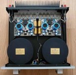
Just from looking at the top picture of the Mimesis85 I can see how well the circuit is laid out. So different from the pcb shown in this thread.
Well, I remember once I hade a tremendousely nice layout on my board. I had been working on it for weeks. And it all went oscillating. Then I shortened the distance between the drives and the end transistors by about 5 mm (another weeks work). And suddenly everything went rock stable, regardless of what load I put on the amp and so on. That gave me the wisdom that I really did know nothing at all.... ;-) I will later give you an example of the circuits I designed. Would be interesting to get your opinion. But we must all know that this was all about 1990. Things may have changed dramatically since then.....
Jay - Those new clean looking MOSFETS you're talking about are all fake 100% from China. Goldmund runs their MOSFETS very hot, if any of you are thinking about using these fake Chinese 2SK134/2SJ49s, beware! These are garbage quality MOSFETS. The amp will sound like a pile of trash and will burn.
Do you have any proof with your assertion? Did you use them?
Faking lateral mosfet? No way! Considering the small size of the market, anyone who fakes TO-3 lateral mosfet for a profit must be insane.
Last edited:
Well, I remember once I hade a tremendousely nice layout on my board. I had been working on it for weeks. And it all went oscillating. Then I shortened the distance between the drives and the end transistors by about 5 mm (another weeks work). And suddenly everything went rock stable, regardless of what load I put on the amp and so on. That gave me the wisdom that I really did know nothing at all....
Bingo.
In every endeavor I have ever undertaken, I have found magic in the most unexpected places. When you find the end of the rainbow, all the theory of the refraction of light goes out the window. Sometimes you just stand in the rain and wonder.
Perhaps this Goldmund amp, including all it's strange, idiosyncratic wrong-ness may be getting something right.
Or, it's overpriced and overrated, and needs improvement.
Either way, I'm still dying to read what someone says about a clone of the original. Tell me there's magic in them there beans, and I'll grow this beanstalk.
Rest assured everyone. If the amplifier is built exactly like the schematic, it'll sound incredible!
If someone wants proof that the Chinese MOSFETS are fake, please buy one on eBay from Hong Kong, then buy another one from a reliable source that has NOS. Maybe someone who has a broken Hafler, or someone on this forum that has stock from a long time ago, etc. Then send these two MOSFETS to me. I will cut off the tops and post pictures for everyone to see how fake the Chinese MOSFETS are. I would not buy any critical components from China, transistors, capacitors, resistors, chips, etc. Especially on eBay. Guaranteed to be 99.9% fake.
If someone wants proof that the Chinese MOSFETS are fake, please buy one on eBay from Hong Kong, then buy another one from a reliable source that has NOS. Maybe someone who has a broken Hafler, or someone on this forum that has stock from a long time ago, etc. Then send these two MOSFETS to me. I will cut off the tops and post pictures for everyone to see how fake the Chinese MOSFETS are. I would not buy any critical components from China, transistors, capacitors, resistors, chips, etc. Especially on eBay. Guaranteed to be 99.9% fake.
Last edited:
Rest assured everyone. If the amplifier is built exactly like the schematic, it'll sound incredible!
If someone wants proof that the Chinese MOSFETS are fake, please buy one on eBay from Hong Kong, then buy another one from a reliable source that has NOS. Maybe someone who has a broken Hafler, or someone on this forum that has stock from a long time ago, etc. Then send these two MOSFETS to me. I will cut off the tops and post pictures for everyone to see how fake the Chinese MOSFETS are. I would not buy any critical components from China, transistors, capacitors, resistors, chips, etc. Especially on eBay. Guaranteed to be 99.9% fake.
OK. That's your sort of proof, buy from an eBayer from Hong Kong and let you pop it open.
Wishing you luck with this amplifier that you promote so much does sound incredible.
Last edited:
- Home
- Amplifiers
- Solid State
- The Very Best Amplifier I Have Ever Heard!!!!