Graham's 'Hot Sugar' Sweet Peach FU50 mod
Ok this I think is the ultimate Peachy mod, this sound beats an £1500 Usher R1.5 150W class A amp weighing 45kg - i.e. it's better than the best transistor amp I've ever heard. This includes heavy rock at loud volume on Usher X-718 speakers (D'Appolito designed). Yes - it's in the living room now so this'll be the end of modding for a while I expect.
For reference it's called the 'Hot Sugar' mod.
OK so to the full mod list, (some were mentioned earlier):
Remember to drain the power supply caps as you'll be touching B1+
General
Input section (6N3s)
Driver section (6N1)
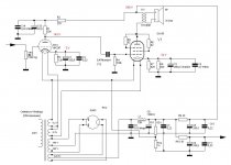
Transformers
We need to reverse the polarity. This also makes the amp preserve absolute phase - it was previously inverting.
Voltages to check
Summary
This leaves the input stage to itself with local feedback. A small amount of NFB then wraps around from speaker to driver making the output section speaker friendly, this is the shortest feedback (2 stage) I found feasible.
Ok this I think is the ultimate Peachy mod, this sound beats an £1500 Usher R1.5 150W class A amp weighing 45kg - i.e. it's better than the best transistor amp I've ever heard. This includes heavy rock at loud volume on Usher X-718 speakers (D'Appolito designed). Yes - it's in the living room now so this'll be the end of modding for a while I expect.
For reference it's called the 'Hot Sugar' mod.
OK so to the full mod list, (some were mentioned earlier):
Remember to drain the power supply caps as you'll be touching B1+
General
- Swap out the fake 0.1u WIMAs and add proper polypropylene instead
- Take out the tiny input caps (also fake WIMA) and short with wire.
Input section (6N3s)
- Change the 1k cathode resistors to 2.2k
- Remove the 220u cathode bypass caps
- Unsolder the FB wires and free from the tyraps
- Optional - remove all FB components (cap, res, big cap)
Driver section (6N1)
- Remove the 6N1
- Rewire for parallel filaments (requires cut track)
- Add an NTC thermistor to the ECC82 only to prevent filament shock
- Replace the 1k cathode resistors for 1.5k at the ECC82
- Remove the 220u cathode bypass caps
- Solder a 5.6k resistor from the grid to the feedback wires
- Insert ECC82/12AU7 driver tube, preferably a classic Mullard
")
Transformers
We need to reverse the polarity. This also makes the amp preserve absolute phase - it was previously inverting.
- Mark then unsolder the red transformers wires from B1+ and the FU50s
- Swap the wires around
- Solder them back - now reversed. This allows NFB to apply to the driver
Voltages to check
- The 6N3 should have a grid at 4.11V and a 14.3x gain
- The ECC82 should have a grid at 5.4V and a 5.2x gain (inside NFB now)
- If you have a scope for 1V at the ECC82 grid you should see 1V at the FB wire. Only 0.21 of that is used as feedback via 5.6/1,5 bridge
- 0.55V across the bias check FU50 resistors to get 55mA. To balance the tubes measure cathode-L to cathode-R and null out, then turn pots equally to bias.
- Total voltage gain should be 14.3 from PCB input to speaker.
Summary
This leaves the input stage to itself with local feedback. A small amount of NFB then wraps around from speaker to driver making the output section speaker friendly, this is the shortest feedback (2 stage) I found feasible.
Many thanks to all of you guys for helping me to get a cheap but I hope not a bad tube amp!
My Peach was delivered by DHL today. So I will start to taste it is it sweet or not.
Also I have ordered a lot of soviet tubes for replacement and probably do later some mods and tube auditions
My Peach was delivered by DHL today. So I will start to taste it is it sweet or not.
Also I have ordered a lot of soviet tubes for replacement and probably do later some mods and tube auditions
Good sound from 6N23P + GU-50 SE by Sergei Klimanski
Sergei Klimanski Blog Archive ????? ?? ??????? ??-50 ( GU-50 ) ? ???????? ????????? ? 6?23?. - Personal web blog
I will use some ideas from this schem to modify my Peach
Sergei Klimanski Blog Archive ????? ?? ??????? ??-50 ( GU-50 ) ? ???????? ????????? ? 6?23?. - Personal web blog
I will use some ideas from this schem to modify my Peach
Attachments
Globulator thank you for your suggestions. I have ordered some caps from different suppliers. You absolutely right, I need to replace a caps and then I will play a little with russian tubes...but I need to say that Peach is sounding surprisingly good just from the box in comparison with my old NAD and new Pioneer.
I think it's a great little amp, my mods just remove the electrolytic caps from the signal path (the cathode bypass ones are partially in the path), reduce by one stage the NFB loop (and reduce the amount of NFB too) and replace the driver tube.
I'm still blown away by the quality - my speakers are not designed for SE operation either (but are very full range and neutral) - I would like to get some genuine GU-50 tubes at some stage too - I just like the idea of using original Russian Power RF radio tubes in there
I'm still blown away by the quality - my speakers are not designed for SE operation either (but are very full range and neutral) - I would like to get some genuine GU-50 tubes at some stage too - I just like the idea of using original Russian Power RF radio tubes in there
I have ordered today
ERSE - PulseX
Any comments? Did somebody use this caps? I understand that it's extremely cheap cap but for Peach it will be probably enough?
PulseX - Metallized Polypropylene Film Capacitor.
ERSE’s Pulse X caps are a premium audiophile grade capacitor designed for quick transient response and ultimate musical performance. Total harmonic and IMD distortion and phase distortion are virtually immeasurable, while all losses are near zero in every aspect. PulseX caps will allow your music to be accurate and uncolored in every way.
ERSE - PulseX
Any comments? Did somebody use this caps? I understand that it's extremely cheap cap but for Peach it will be probably enough?
I have ordered today
ERSE - PulseX
Any comments? Did somebody use this caps? I understand that it's extremely cheap cap but for Peach it will be probably enough?
My new caps were basic wound polypropylene ones - Erse are used in some Usher speakers so they must be pretty damn good as in my experience of hifi shows and subsequent purchase Ushers sound as good as the best for a fraction of the price.
So yes - I'd go for those Erse caps in your link!
Hello,
Please excuse my English but I'm Portuguese and I have to use the google translator.
I am a new user of the forum and ordered a sweet peach.
I have little knowledge of electronics but I would like to change the capacitors.
I have no problem in doing the welding, but I do not know exactly what capacitors to buy, maybe the ERSE?
I also do not know if these capacitors have polarity and if this is marked on the board.
If someone can post a picture of the board with the capacitors signed and the polarities marked that would be a huge help.
Thanks,
Alexandre
We call it soldering, not welding!
Which part of Portugal are you in? I bought some good caps in Porto - there's a very good shop there I found.
The caps just need to be rated > 400V, ideally >600V.
I use 1kV polypropylene as I had them - mine were cheap too. The ERSE caps seem fine to me.
No polarity.
Please discharge the big PSU caps safely, after switch-off wait 1 minute, then connect a resistor (between 1k and 10k) between ground and the red connector to the middle of the driver board.
Use a multimeter to confirm it has no voltage.
Last edited:
Sorry but I'm not living in Portugal I am living in Switzerland, this is part of the problem my German is much worse than the English and therefore have to rely only on the Internet to buy components.
How many watts should have the resistor to make safely the discharge of capacitors?
Can you help me with instructions on how to adjust the bias this amplifier?
Thanks
How many watts should have the resistor to make safely the discharge of capacitors?
Can you help me with instructions on how to adjust the bias this amplifier?
Thanks
Ah - feel free to PM me with details about how to emigrate to Switzerland
Just buy a 1 or 2Watt resistor - it should be fine. Make it so that you can discharge the caps without touching anything metal like the leads, and measure with a meter afterwards.
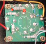
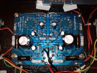
The bias should be about 55mA (although I suspect 50mA would be fine). There is a 10 ohm resistor on the FU50 boards - see picture - measure for 0.55V (or 0.5V for 50mA) across the resistor - where the red blobs are.
BTW that red lead on the left side is the full anode voltage from the transformer and will have about 430V sitting it it, connected to a large capacitor - please stay clear of that, you'll live longer
Just buy a 1 or 2Watt resistor - it should be fine. Make it so that you can discharge the caps without touching anything metal like the leads, and measure with a meter afterwards.
The bias should be about 55mA (although I suspect 50mA would be fine). There is a 10 ohm resistor on the FU50 boards - see picture - measure for 0.55V (or 0.5V for 50mA) across the resistor - where the red blobs are.
BTW that red lead on the left side is the full anode voltage from the transformer and will have about 430V sitting it it, connected to a large capacitor - please stay clear of that, you'll live longer
Attachments
Last edited:
Thank you for your help.
To make the discharge of capacitors I was thinking that I could connect an insulated wire with the resistor from the ground on the box to the red wire, is it ok?
Bias adjustment is done in those two variable resistors of the second photo?
I'm planning to replace the two small capacitors with wire, replace the fake 0.1u WIMAs and exchange the valves for equivalent of Soviet origin.
Thanks
Attachments
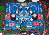
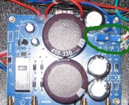
I am done with caps!
So my feeling that this caps are much better then stock Wimas...
I did comparison for one channel first using a good Sennheiser's headphones and I found that it is easy to see the difference. The new caps can give you more air and more details. Vocal is perfect now, it was not bad but now it is GOOD!
Attachments
My WIMAs were fake or rejects - they were not genuine, the real WIMA sounds good too
I swapped out my 6N3 tubes for the nice russian 6N3P-DR ones - they have lovely little round 'hats' above the main mica former on top so they look stronger and nicer. They sound better than the Chinese ones too - vocals are more realistic and the whole sound is a little clearer. Bear in mind I'm biasing mine differently than stock (ref Hot Sugar mod), with no bypass capacitor and it's no longer in the feedback loop either - so this stage is quite audible in my Peach!
The only remaining tube mod is for GU50s - as I run less feedback now these should be improvable, although the FU50s sound very very good.
I also got a 6n6p - not going to use it just yet but what a big tube, probably why people find it better than the old 6n1p, the ECC82 I use also has large plates, maybe better for driving the output tubes.
I am waiting the parcel from Russia with number of tubes from different years and plants and I will spent some time to play with soviet tubes Also my friend from Moscow promised to find and send to me a few 6N30P for reasonable price. This tube is a military version of 6N6P. Many peoples believe that it's the best Russian driver tube ever. Right now I will not touch any bypass capacitors in any feedback loops but I will to change this caps for a better quality brand caps or even may be for non-polar film caps.
Also my friend from Moscow promised to find and send to me a few 6N30P for reasonable price. This tube is a military version of 6N6P. Many peoples believe that it's the best Russian driver tube ever. Right now I will not touch any bypass capacitors in any feedback loops but I will to change this caps for a better quality brand caps or even may be for non-polar film caps.Sorry missed the other questions:
Yes, try to make the ground lead the long one, so you are only holding the ground lead when you use it!
Yes.
But changing one affects the other!!
So firstly balance the two tube biases together by measuring from tube tab to tube tab (the right hand -> red dot on my picture). I.e from that point measure for 0.00V between the cathode of FU50 tube 1 and the cathode of FU50 tube 2.
Then measure between the red dots as in my picture, (little clips are useful for this) and turn both knobs the same amount to set the bias - 0.55V for 55mA.
One day I'll change my 10ohm resistor for a 1ohm - it doesn't need to be so big!
Thank you for your help.
To make the discharge of capacitors I was thinking that I could connect an insulated wire with the resistor from the ground on the box to the red wire, is it ok?
Yes, try to make the ground lead the long one, so you are only holding the ground lead when you use it!
Bias adjustment is done in those two variable resistors of the second photo?
Yes.
But changing one affects the other!!
So firstly balance the two tube biases together by measuring from tube tab to tube tab (the right hand -> red dot on my picture). I.e from that point measure for 0.00V between the cathode of FU50 tube 1 and the cathode of FU50 tube 2.
Then measure between the red dots as in my picture, (little clips are useful for this) and turn both knobs the same amount to set the bias - 0.55V for 55mA.
One day I'll change my 10ohm resistor for a 1ohm - it doesn't need to be so big!
Last edited:
Thanks for the help,
I'll use two multimeters and some test lead clips to make the measurements, I think my skin is well worth the price of a new multimeter.
I was thinking about buying the ERSE but they only accept minimum orders of $55 to Switzerland, after some research I ordered four Mundorf MCAP Supreme 0.10uF/1200V, I hope they are appropriate.
Thanks again for your help, when I start with the modifications of the amplifier I'll see if I can take some pictures, maybe they can be useful for someone who is starting from scratch.
I'll use two multimeters and some test lead clips to make the measurements, I think my skin is well worth the price of a new multimeter.
I was thinking about buying the ERSE but they only accept minimum orders of $55 to Switzerland
, after some research I ordered four Mundorf MCAP Supreme 0.10uF/1200V, I hope they are appropriate.Thanks again for your help
, when I start with the modifications of the amplifier I'll see if I can take some pictures, maybe they can be useful for someone who is starting from scratch.- Status
- This old topic is closed. If you want to reopen this topic, contact a moderator using the "Report Post" button.
- Home
- Amplifiers
- Tubes / Valves
- Trying to make sense of the Sweet Peach