Yes great delivery and in good shape - TNT parcels.
So your line up with an unmodified amp is all Russian, one 6n6p, two 6n3p and two GU50.
The FU50 is chinese - the GU50 the russian yes?
I assume the Single Ended bias point is so the plate/OPT voltage is in the middle then - so if it gets 430V I should get 215V at the middle. I'll see where it is first at 220V input then.
I'll try it tomorrow - got a few bits to move around first! If I order russian tubes I'll get the set you have - probably from siberian-shop when the volcano dies down!
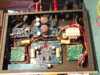
I think the little phono amp runs off the 12.6v filament voltage, interesting but it'll have to go. It'll free up some space too, making it a bit less cluttered.
Nice neat construction though - I think it looks really good.
Still want a 6n6p though - or something to get the 6n1 biased well!
So your line up with an unmodified amp is all Russian, one 6n6p, two 6n3p and two GU50.
The FU50 is chinese - the GU50 the russian yes?
I assume the Single Ended bias point is so the plate/OPT voltage is in the middle then - so if it gets 430V I should get 215V at the middle. I'll see where it is first at 220V input then.
I'll try it tomorrow - got a few bits to move around first! If I order russian tubes I'll get the set you have - probably from siberian-shop when the volcano dies down!
I think the little phono amp runs off the 12.6v filament voltage, interesting but it'll have to go. It'll free up some space too, making it a bit less cluttered.
Nice neat construction though - I think it looks really good.
Still want a 6n6p though - or something to get the 6n1 biased well!
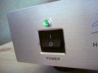
FWIW mine came in biased at about 56ma at idle which is very close to what Svein _B calculated for the GU50, no real instructions included, did you get those two strange sample discs of music with yours too? I need to get rid of that gaudy blue LED as well, I was gonna go with a red replacement.
I assume the Single Ended bias point is so the plate/OPT voltage is in the middle then - so if it gets 430V I should get 215V at the middle.
Wrong!
The DC voltage at the anode will be close to the B+.
To measure the idle current you measure voltage across the cathode resistor.
If the resistor is 10 ohm, 0.8V will correspond to 80mA.
SveinB.
Cheers Svein, I'll aim for around 55mA - it has the 10R resistors for that purpose - they just omitted to tell me the bias current!
BTW if the anode is near B+ surely it will just clip? Or is the maximum swing far less than I'm thinking on a single ended?
Please let me know if you have some ideas about for to push the 6N1 into a more linear region, I'll probably order a 6n6p anyway tonight though as that seems to match better.
BTW if the anode is near B+ surely it will just clip? Or is the maximum swing far less than I'm thinking on a single ended?
Please let me know if you have some ideas about for to push the 6N1 into a more linear region, I'll probably order a 6n6p anyway tonight though as that seems to match better.
Finally powered up the Sweet Peach on the Variac, no drama but I did notice the following:
For an exact 12.6V heater voltage it needed 230V, 245V was over 13V.
I understand the bias now - the drive is a current drive into the OPT, not a voltage drive - not sure how I missed that one!! It is designed to idle at 59mA at 230V input (assuming they aimed for 12.6v heaters), both tubes were set up perfectly for that. Maybe I'll buck it by 12V so my 245V turns into 233V, as 220V was a bit low.
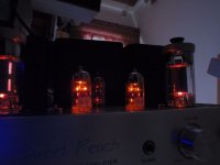
I had it plugged into some shelf speakers and then some old Kef Concertos - they sounded pretty similar to transistor amps I've used in the past except the treble and midrange was much sweeter. I was playing rock and pop, the thing that stood out over transistor was the voices - much better!! The mains transformer only got a tiny bit warm, the rest of the heat came from the FU50s.
I wasn't bothered by the blue 'on' light at all - strangely!
Sound seemed to sharpen up a tiny bit going from 220V to 235V input but that could have been my imagination. I'll need to plug it into my proper Usher 718 speakers for the next test.
Oh and one odd thing - I was testing it with my iPod - from a 3.5mm jack to twin phono into the Aux, and I got this heartbeat once-per-second superimposed on the sound track. Thump, thump, thump etc.
Plugging into the 3.5mm to 3.5mm MP3 input and the heartbeat was gone and it sounded fine - but I noticed a lot of capacitors on that input - so what do you think is going on there then?
For an exact 12.6V heater voltage it needed 230V, 245V was over 13V.
I understand the bias now - the drive is a current drive into the OPT, not a voltage drive - not sure how I missed that one!! It is designed to idle at 59mA at 230V input (assuming they aimed for 12.6v heaters), both tubes were set up perfectly for that. Maybe I'll buck it by 12V so my 245V turns into 233V, as 220V was a bit low.
I had it plugged into some shelf speakers and then some old Kef Concertos - they sounded pretty similar to transistor amps I've used in the past except the treble and midrange was much sweeter. I was playing rock and pop, the thing that stood out over transistor was the voices - much better!! The mains transformer only got a tiny bit warm, the rest of the heat came from the FU50s.
I wasn't bothered by the blue 'on' light at all - strangely!
Sound seemed to sharpen up a tiny bit going from 220V to 235V input but that could have been my imagination. I'll need to plug it into my proper Usher 718 speakers for the next test.
Oh and one odd thing - I was testing it with my iPod - from a 3.5mm jack to twin phono into the Aux, and I got this heartbeat once-per-second superimposed on the sound track. Thump, thump, thump etc.
Plugging into the 3.5mm to 3.5mm MP3 input and the heartbeat was gone and it sounded fine - but I noticed a lot of capacitors on that input - so what do you think is going on there then?
no real instructions included, did you get those two strange sample discs of music with yours too?
I did not appear to have any paper or CDs!
Well I got the USB lead and a mains lead (US + multi-adapter)!
I'm just trying to work out what the mods actually are!
Replacing the 47k with a 27k for the 6n1 I think was one, alternately just using a 6n6p. Also caps are obvious targets - including the electro bypass - I wonder if leds + a smaller poly cap may work better?
We'll have to create the ultimate mods list!
I've had some more listening now - still on the old Kefs, I think maybe a zobel will be needed later on but we'll see.
I've ordered a 6n6p as there is no way to make the load line of the 6n1p linear, even with a 27k anode resistor or even a CCS.
The 6n6p lines look more promising, but only definitely when a CCS is used.
I only get the full 400V arriving at the 6N1P anode resistor when I run from 245V (actually I get 397V), but then heater voltage is at 6.7V and 13.5V - although these are still within spec - just a bit brighter that 6.3 and 12.6
With 245Vac mains I get 63mA current in the tubes and also 198V at the plate of the 6N1P at a 4V cathode, which puts it in a non-linear place.
This was my experience as well, it is puzzling that the 6n1p would be allowed to operate in this portion of the curve. Strangely, as was posted earlier, Svetlana has a generic schematic for the 6n1p that uses these exact values. I do not doubt the 6n1p can sound great but judging by the curves and data sheet I think it takes some careful design work. The 6n6p on the other hand looks like a model citizen and should be much easier to implement, Lukuzs Fikus ( Mr. Lampizator) seems to love the 6n6p.
I do not understand how some of you guys have got the presumption that the operating conditions for the 6N1P are poor.
I think the tube has a decent operating point, and is reasonably linear.
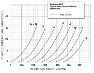
I posted a curves from the Russian datasheet with loadline in page#1 of this thread. Below is another one based on measured tube curves, but a different vertical scale. This is also with 4V at the cathode and 50K load. Looks OK to me.
For those new to tube curves and loadlines, observe that linearity is understood as variation in anode voltage as a function of grid voltage when moving along the loadline.
The curves are from the excellent collection of Russian tube data at : Klausmobile Russian Tube Directory
SveinB
I think the tube has a decent operating point, and is reasonably linear.
I posted a curves from the Russian datasheet with loadline in page#1 of this thread. Below is another one based on measured tube curves, but a different vertical scale. This is also with 4V at the cathode and 50K load. Looks OK to me.
For those new to tube curves and loadlines, observe that linearity is understood as variation in anode voltage as a function of grid voltage when moving along the loadline.
The curves are from the excellent collection of Russian tube data at : Klausmobile Russian Tube Directory
SveinB
Attachments
I do not understand how some of you guys have got the presumption that the operating conditions for the 6N1P are poor.
Your graph does indeed look good, but I got the presumption (or postsumption) from this graph here...
BTW: How did you come by your graph?
Attachments
Last edited:
BTW I was planning to measure the actual voltage swings at each stage, but my old Tektronix 7603 scope decided to stop working.
Then I found a fault in the scope PSU board and fixed it (dry joint), plugged it back and and blew the scope, as I there is an ambiguous red connector that I managed to put in about 2 pins offset to where it should have been. So no more scope (or even less of a scope than it was before).
So I'm after a scope now, ideally small, modern and reliable - ideas please!!
I'm also a little confused, the graph I have been using is nearly identical to the Svetlana graph shown above by Globulator. I thought the difference I was seeing is just due to very different scale/ resolution but if you follow the 0v grid curve it intersects 10ma at about 120v, that same curve intersects 10ma at about 100v on the Klausmobile graph.
I wonder if he looked at the wrong graph?
The 6SN7 looks like the perfect driver tube to me, OK it's bigger and needs a different socket, but it does seem to fit the job as long as the gain is high enough - that's the remaining question.
A 12bh7 may also fit with a pinout mod - similar gain though.
What does seem to be clear however is that we need a CCS to make this run better - regardless of tube - SY's recent phono-amp includes some current sources we could adapt - good up to 400V too.
It's an awkward combination of high voltage (400V, 200V plate) with the tubes we are using needing high current to make them linear - the 6SN7 seems to like the FU50 driver operating point though.
Modding the Sweet Peach
OK so while browsing the tube specs and load lines I found the 12AU7 or ECC82 was quite happy around the 200V, 4mA region - plus - I actually have three Mullards sitting in a box.
So I first had to mod the board - pin 9 was unconnected but on the ECC82 is the filament centre tap - so a cut track and a couple of wires later and the socket is ready for the ECC82 with parallel filaments...
..So I plug it in and gingerly wind up the Variac - all good, and it sounds nice too. I get 141 on the plate and 4.5 on the cathode, so I look at the lines and replace the cathode resistors for 2.2k ones, and get 8.23V cathode, and about 200 at the anode. It sounds a little more detailed now - the load lines want a CCS but it's better with this tube.
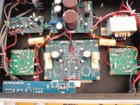
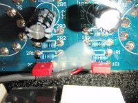
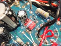
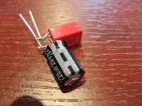
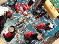
So I decide to change the red 'Wima's next, as one was a different size and they looked like rejects. The new ones are polys I bought from Rapid 0.1u 1kV, so once in and tried it out, WOW - what a massive stonkingly HUGE difference. Real bass now, far more balanced sound - I guess the old ones were not really Wima at all were they - dustbin for those!!
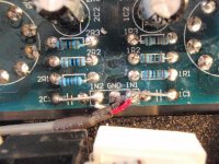
Then I noticed some extra caps on the input - next to a glob of glue. Well they have to come out now obviously - so a heat gun got the glue soft (it's hot-glue) and some component lead wire replaced the caps.
Then I looked at the electros in the signal path, there are two cathode bypasses and 1 feedback 220uF - so some new Jamicons went in with some genuine Wima 0.68uF bypass caps (I only had 4 Jamicons so the FB capacitor stayed there. Space was a bit tight and I had a couple of spare 400V 22u caps so I also changed the bulky ones for those - much smaller and possibly better.
So again slowly wound up on the Variac, and what a good sound!! Bassy, clean detailed, smooth - and this is through the old Kefs that sounded pretty dull when I started!!
Mod summary:
And it sounds awesome")
Next mod is for 4-5mA CCS and LED cathode voltage
Not sure why they split the 6N3 tubes either - only half is used each side!
OK so while browsing the tube specs and load lines I found the 12AU7 or ECC82 was quite happy around the 200V, 4mA region - plus - I actually have three Mullards sitting in a box.
So I first had to mod the board - pin 9 was unconnected but on the ECC82 is the filament centre tap - so a cut track and a couple of wires later and the socket is ready for the ECC82 with parallel filaments...
..So I plug it in and gingerly wind up the Variac - all good, and it sounds nice too. I get 141 on the plate and 4.5 on the cathode, so I look at the lines and replace the cathode resistors for 2.2k ones, and get 8.23V cathode, and about 200 at the anode. It sounds a little more detailed now - the load lines want a CCS but it's better with this tube.
So I decide to change the red 'Wima's next, as one was a different size and they looked like rejects. The new ones are polys I bought from Rapid 0.1u 1kV, so once in and tried it out, WOW - what a massive stonkingly HUGE difference. Real bass now, far more balanced sound - I guess the old ones were not really Wima at all were they - dustbin for those!!
Then I noticed some extra caps on the input - next to a glob of glue. Well they have to come out now obviously - so a heat gun got the glue soft (it's hot-glue) and some component lead wire replaced the caps.
Then I looked at the electros in the signal path, there are two cathode bypasses and 1 feedback 220uF - so some new Jamicons went in with some genuine Wima 0.68uF bypass caps (I only had 4 Jamicons so the FB capacitor stayed there. Space was a bit tight and I had a couple of spare 400V 22u caps so I also changed the bulky ones for those - much smaller and possibly better.
So again slowly wound up on the Variac, and what a good sound!! Bassy, clean detailed, smooth - and this is through the old Kefs that sounded pretty dull when I started!!
Mod summary:
- Rewire board for ECC82 and add ECC82
- Change 1k cathode resistors for 2.2k
- Change fake 0.1u Wimas for real Poly caps
- Remove C1 input caps and use wire instead
- Change 220uF bypass caps for Jamicons
- Bypass all 220uF caps with genuine Wima 0.68u
- Change 400V 22uF PSU caps
And it sounds awesome
Next mod is for 4-5mA CCS and LED cathode voltage
Not sure why they split the 6N3 tubes either - only half is used each side!
Attachments
-
 GPW_mods_01.jpg39.2 KB · Views: 976
 -
 GPW_mods_02.jpg83.7 KB · Views: 983
 -
 GPW_mods_03.jpg68.8 KB · Views: 959
 -
 GPW_mods_06.jpg76.1 KB · Views: 427
 -
 GPW_mods_05.jpg62.8 KB · Views: 422
 -
 GPW_mods_04.jpg74.3 KB · Views: 419
 -
 GPW_mods_07.jpg83.8 KB · Views: 440
 -
 GPW_mods_08.jpg89.9 KB · Views: 534
 -
 GPW_mods_09.jpg27.9 KB · Views: 473
Last edited:
I'm impressed, you are a little more ambitious than me Globulator!! I was going to snip out the tiny caps in series with the line level inputs as well but forgot when I was replacing the coupling caps which as you mentioned have a considerable impact on sound quality. Did you find replacing the cathode bypass caps to be worth the effort?
Nice to see you spending real quality time with your amp!
I too had my fingers on the C1 but decided not to remove them at the same time as changing the 0,1uf to mkp, now I feel like I have to remove them too.
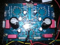
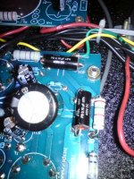
Sorry I take 90% of my pictures with my phone.. not that great.
On the image where the new green light is showing, you can also barely see the new rubber feet I have put under the amp to get more air underneath it.
One image shows it with the stock "wima's", one shows the new caps installed on one channel, the other side of the board looks the same.
I too had my fingers on the C1 but decided not to remove them at the same time as changing the 0,1uf to mkp, now I feel like I have to remove them too.
Sorry I take 90% of my pictures with my phone.. not that great.
On the image where the new green light is showing, you can also barely see the new rubber feet I have put under the amp to get more air underneath it.
One image shows it with the stock "wima's", one shows the new caps installed on one channel, the other side of the board looks the same.
Attachments
- Status
- This old topic is closed. If you want to reopen this topic, contact a moderator using the "Report Post" button.
- Home
- Amplifiers
- Tubes / Valves
- Trying to make sense of the Sweet Peach