Hola Wagonpilot...
Check your driver boards to see which version they are. They should be PC19c, if that is correct then P1 is for dc offset and P2 is for bias. Opinions will vary set P1 with no signal and no load to as close to 0.000v as possible and a good starting place for bias
is to allow about 50mA for the board and 50mA for each output device. The DH500 has 6 output devices ~350mA as a starting place to be safe, then experiment from there. There are some good pointers in this thread, however long and painfull reading at times. Keep us posted with your results...
Regards, Elwood
Hafler used the same circuit card layout for both DH-200/220 and the DH-500. Early versions of the DH-500 used the circuit card layout of the DH-200. Later versions of the DH-500 used the circuit card layout of the DH-220.
The DH-200 style layout only has one variable resistor, only a P1 more or less in the center of the card. It had no way to null out DC offset.
If you are stuck I can rustle up an add-on little circuit to null out DC offset, or you can get some sets of the initial 4 small signal transistors that are matched on hFe.
Thanks folks!
Both my 220 and 500 have PC 19B boards in them. I guess they are a little older than amps with the PC 19C boards.
all my boards do have both P1 and P2 trim pots.
I am not able to get one channel of the 220 to anything less than ~ 60 mV. I guess it is time to get some of those 25 year old components out of the game and onto the bench. New differential transistors and recap in order?
I was a bench tech at our school 15 years ago, and have not used that knowledge directly since then. This has been lots of fun getting back into it and learning a lot of this stuff again. This is a good platform for it.
I rebuilt a DH 110 preamp a couple of weeks ago and that was fun. Sounded LOADS better. It reminded me my old soldering skills too.
Thanks again,
c
Could you tell what you did to the 110 pre - I've got one sitting here with an intermittent switch problem and good time to maybe upgrade it a bit.
I've also got a 220 amp looking for new caps (& maybe rail Cmultipliers) and a simplified wiring upgrade - thinking about that new driver stage addition plus the front end rail reg.
Need a new extended bottom plate to create more room for the trannie and extra cap.
Good gear. Pain in the A. with the small frame!
So there really are people out there using Dh110's.
I started a thread awhile back on mods and nobody responded maybe it's time to start another one.
I have had problems with intermittant switches as well, Cramolin will clean them up well.
also the muting jfet's go out a lot , I just removed mine.
I started a thread awhile back on mods and nobody responded maybe it's time to start another one.
I have had problems with intermittant switches as well, Cramolin will clean them up well.
also the muting jfet's go out a lot , I just removed mine.
DH110
It seems that the DH110 is still in use, altho not so common out here in Oz. It seems to do a quite reasonable job of managing the signals from the newer formats without tearing your ears off.
Didn't think to check those muting fets - hmmm... I'll see if I can find your old thread.
Was thinking about a really good supply, but probably need a higher voltage trannie - and the usual renewal of the electro caps - there's a bit of room for some better PP caps, too. Where do you stop?!
I bought my 110 on Ebay, it was a very clean unit but had dirty switches and pots. I was unimpressed with the sound as well.
At the time I was running a set of Martin Logan Quests with Sumo power.
On the mods, I kinda cheated. There is a guy on Ebay that is selling a kit. It has new caps and a complete set of instructions for the work. It also removes the muting circuit.
The sound on MINE was improved vastly. Night and day.
I also hit the switches and pots with Deoxit. They cleaned up nicely as well.
yeah that was my impression as well.
this thread is probably a better place though
a little off topic here
http://www.diyaudio.com/forums/showthread.php?s=&threadid=139454
this thread is probably a better place though
a little off topic here
http://www.diyaudio.com/forums/showthread.php?s=&threadid=139454
HI Folks,
First post here! Thanks for all this good information.
I got a DH-200 recently and have found this thread invaluable, I've read it all and I am taking slowhands approach below as not to mod the amp beyond recognition.
Condition when bought:
Running very warm
Slight hum buzz
18 AWG Lamp cord
All stock
1st pass at update:
Result so far:
Amp is extremely quiet, I had to put my ear to the speaker to see if it was on and nothing, no hiss, hum, or buzz.
Amp runs barely warm, from extremely warm before. Not sure what that is due to as at 232 mA it ran very warm before. I did not recheck the Bias after the AC work.
It sounds great, it gives my PMA-2000IVR a run for its money in A/B comparison.
Phase 2 of updates are next. I plan to keep the amp as original as possible, DC offset is 11 mV and 75 mV, so it should do OK as some I hear left the factory with as much as 100-200 mV of offset.
I will order some gold RCA jacks and binding posts from Parts Express. Any part numbers anyone recommends for this?
Thanks.
First post here! Thanks for all this good information.
I got a DH-200 recently and have found this thread invaluable, I've read it all and I am taking slowhands approach below as not to mod the amp beyond recognition.
Condition when bought:
Running very warm
Slight hum buzz
18 AWG Lamp cord
All stock
1st pass at update:
- 12,000 uF 60/85 VDC main caps
- 470 uF 100 VDC Nichicons parallel on each main caps
- Replaced all electrolytics except 470/6.3 BP, on order
- Install 14 AWG 3-prong AC cord
- Chassis grounded to green ground wire on new cord
- Replace input wires with micro coaxial cable
- Made a solid coper ground bus between main caps
- Removed RCA jack input grounds to chassis via 2.2 ohm resistor, ran ground wires to both input points (#2) on cards with 3.9 ohm resistors
- Set BIAS to 232 mA, will set to 275 mA later
Result so far:
Amp is extremely quiet, I had to put my ear to the speaker to see if it was on and nothing, no hiss, hum, or buzz.
Amp runs barely warm, from extremely warm before. Not sure what that is due to as at 232 mA it ran very warm before. I did not recheck the Bias after the AC work.
It sounds great, it gives my PMA-2000IVR a run for its money in A/B comparison.
Phase 2 of updates are next. I plan to keep the amp as original as possible, DC offset is 11 mV and 75 mV, so it should do OK as some I hear left the factory with as much as 100-200 mV of offset.
I will order some gold RCA jacks and binding posts from Parts Express. Any part numbers anyone recommends for this?
Thanks.
I have repaired a lot of these, and done a few minor mods. I suggest several basic mods that add reliability only, since most of the the perfomance improvement mods I tried made it an oscillator, not an amplifier.
First, here is my list of the most common failures in these amps, with causes. The power switch fails, due to excessive inrush currents (see fix below). The output transistors do burn out, probably due to insufficient cooling coupled with oversized fuses on power. The input pairs go leaky due to overdriven inputs. When the outputs fail, they generally take out drivers and possibly inputs, as you would expect. That's what I see most often, so those are the areas I check first.
There is not a lot you can do to hugely improve the sound of this amp, in my opinion. Here are some small mods that preserve the essential character of the design while adding reliability.
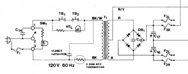
The first mod is simply an NTC thermistor (5 ohm cold) on the AC power. This is needed to prevent the switch from failing due to high inrush current. On most of the amps I see, the power switch is toast and has to be replaced, but it will just fail again unless you do this mod. If you do nothing else, do this mod!
The second mod is a MOV across the transformer primary, in parallel with an X Cap of 0.047 400v. I also put the same value X cap across the rectifier bridge AC inputs. This removes switching transient noise on power on and off, and protects from line surges and noise.
The third mod concerns basic ground wiring. As designed, this amp does not have a single point star ground philosophy, but instead daisy chains ground. This is not wise practice from a noise standpoint. This amp uses a single ground wire to the speaker common, then to the board output power side. The input ground is provided via the output ground and a 2.2 ohm resistor. I don't like this practice, so I add a front-end ground return wire to star ground. In some cases this stops a hum or buzz. In addition, I tie the chassis ground lug on the output transistors terminal strip to the output ground, rather than depending on the chassis and screws to provide this ground. Finally, I use gold plated floating input jacks and tie the input signal return to chassis ground via 2.2 ohm resistors on both channels, breaking internal and external ground loops. I use a copper bus bar between both cap ground lugs to set up a star ground point midway between them. All grounds return to this point, although I use a second lug for the input grounds to avoid the high ground currents flowing to and from the center tap wire.
As designed, this amp sends the output to the fuse on the back panel, then back to the board and zobel net, then to the output binding post on the back panel. The intent was to include the fuse in the global feedback loop, in concept a good idea, but as implemented here not so good. This can result in radiated noise from the high level output signal to the input wiring or other points. I delete this feature, sendiing the output (twisted with output return lead) direct to the fuse then the binding post. This hopefully reduces one major source of distortion (per Self). You have to add a jumper on the board to bypass this fuse loop when you do this mod.
I sometimes rewire these to allow bridged operation, with a switch on the back panel to switch from mono to stereo. Use the instructions on the Hafler website for the DH220 bridging, but change the resistor to 2.2k for the DH200.
http://www.hafler.com/techsupport/pdf/DH-222_bridgeKitForDH-220.pdf
Some History: There are several versions of the driver board for this amp. The DH200 used a "PC6" driver board, which lacks certain features detailed below. The early versions of the DH 220 used the PC6, but switched to the "PC19" board in midlife. (I have DH220 manuals showing both versions.) These driver boards are very similar in topology, but have some minor differences that slightly improve sound in the later version. PC19C is preferred.
The very early (1978) versions of the PC6 used a mix of low voltage transistors on the input side (MPS8X99, BC456/556). These have higher beta but lower breakdown voltages. While the higher beta probably resulted in lower distortion and lower output offset voltage, they were less robust than the types used in the later PC19 (which used 2n5401/2N5551 except for the Vbe multiplier). I generally replace with the more robust parts when doing repairs.
Here is a list of the significant differences between the driver boards:
1. PC6 uses low voltage transistors in the front end, while PC19 uses the higher voltage parts.
2. The PC6 uses a bipolar electrolytic input cap, the PC 19 uses a mylar cap.
3. PC19 has an added output offset adjust pot.
4. The Darlington VAS uses a Baker clamp in the PC-19, to improve recovery from overload.
5. The output transistors have power bypassing on the DH-220, while those in the earlier DH200 do not. These are 0.1mf, 100v mylar caps to chassis ground. For stability, you should add these if they are not present.
6. Early PC6 boards used ceramic caps, which were changed to mylar or mica in later versions. In general, mylar bypasses were added across electrolytics in the later version.
All of these differences are evolutionary refinements and do not make cosmic differences in the sound, but are "nice to have". I suggest looking for the later driver boards if you are buying one of these.
I am very wary of major mods to this amp, because it seems to be on the verge of instability. I often see a very low level 60 MHz oscillation on the output of this amp, but it could me a measurement artifact. If you take out any of the low-pass filters on the input stage, it oscillates. If you remove the caps to ground on the VAS, it oscillates. Miller caps on the VAS don't seem to cure this. I think this is partly due to the physical layout and partly due to the high open loop gain of the circuit itself. Certainly the relatively long wires to the output transistor array are great antennas, right beneath the board. So, I pretty much leave the amp stock except for the mods discussed above.
I hope someday to lay out a new PC for this amp that uses flat pack lateral mosfets to eliminate the wiring to the output transistors which seems to contribute to the tendency to oscillate that I mentioned. To me that seems a better approach than hacking the present boards.
WE should hold Slowhands to his word , Where are our boards???
our next best bet is fab and his mods, Maybe First bet...
this is an extensive thread maybe some kind soul would do a condensed version with best mods or start a new tread with some serious direction towards a penultimate dhxxx ...
Just trying to stir it up...
Regards, Elwood
our next best bet is fab and his mods, Maybe First bet...
this is an extensive thread maybe some kind soul would do a condensed version with best mods or start a new tread with some serious direction towards a penultimate dhxxx ...
Just trying to stir it up...
Regards, Elwood
Boards for DH-200/220 mods...
I am sorry... I forgot about that...
I am into other projects right now. I am exploring class A more and more...
WE should hold Slowhands to his word , Where are our boards???
our next best bet is fab and his mods, Maybe First bet...
...
Regards, Elwood
I am sorry... I forgot about that...
I am into other projects right now. I am exploring class A more and more...
On the DH-200, is it a sonic improvement to bypass all the electrolytics with a .1 uF film capacitor? Or just the input cap? How about the main capacitors, do they benefit from this bypass? Currently I have them paralleled with a pair 470 uF 100v electrolytics.
The orders are in to Mouser and Parts Express, will post pics soon.
Thanks.
The orders are in to Mouser and Parts Express, will post pics soon.
Thanks.
About the 470uF bipass on your main power caps - suggest you use a "fast" switch mode type cap for this like a Rifa peg124 but they will need a series resistor to dampen them - normally about 1.5 -> 1.8 ohms, (the Phillips 2w metal film is my usual Resistor here). Unfortunately, these sort of caps take ages to "form up" (well over 100 hours) so more "standard" caps still work well, but don't add the increased top end detail.
On the MKP bipass caps, I also add a small 0.1 - 015R series resistor - not so easy to find, however - and found that 2 // 0.33R SMD (tiny things) soldered together (with added "legs") match up quite well with the small Wima MKP10 capacitor that are readily available - these tack onto the underneath easily with a small peice of insulation tape for safety.
Surprising thing, I found this works very well with the caps next to the digital chips in the CD players, too.
I'm mainly into Class A amps now where the effects of these "R+C snubbers" is quite noticeable but with a bit of patience, the benefits in class AB amps can also be remarkable.
Hola Y'all...
Fab...just picking I got more than a full plate and I'm looking at Sonderklass A as a vent to build something. Transistors are cheap in the big scheme of things but Transformers and heat sinks are the largest roadblock to building .
That being said I hope to resurect my Yamaha B2 and use my Hafler for bottom end duty in a bi amp system.
Keep up the great work, Elwood
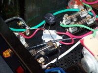
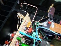
My power feed mods are done. 3-prong 14 AWG power cord, 5 ohm NTC thermistor and X class capacitor on AC feed line. I need to somehow take the output transistor ground chassis tap off and come off the new ground bus on the main caps. Only problem is the connector itself is screwed on to the the heat sink now receiving house ground via chassis. I am isolating all grounds to the new ground bus made from a flattened 1/2" copper water pipe.


Attachments
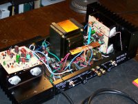
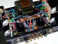
The Hafler DH-200 is done. With advise from this thread and others, here is what I've done:
Sound is awesome even with caps not broken in. Very quiet and powerful. Nice laid back disposition like that of tubes. Love it.
Thanks for all your help.
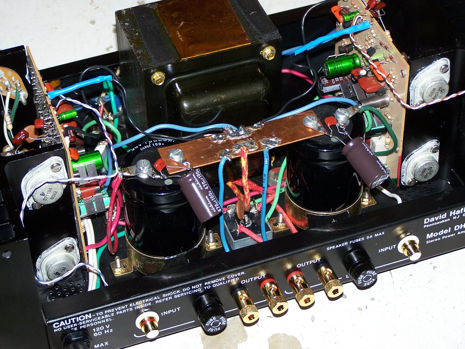
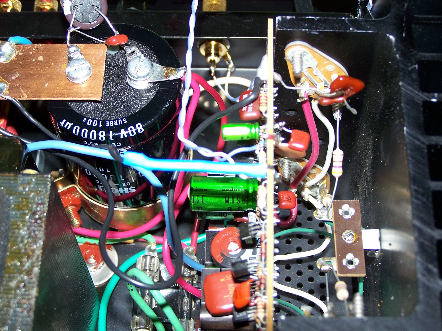
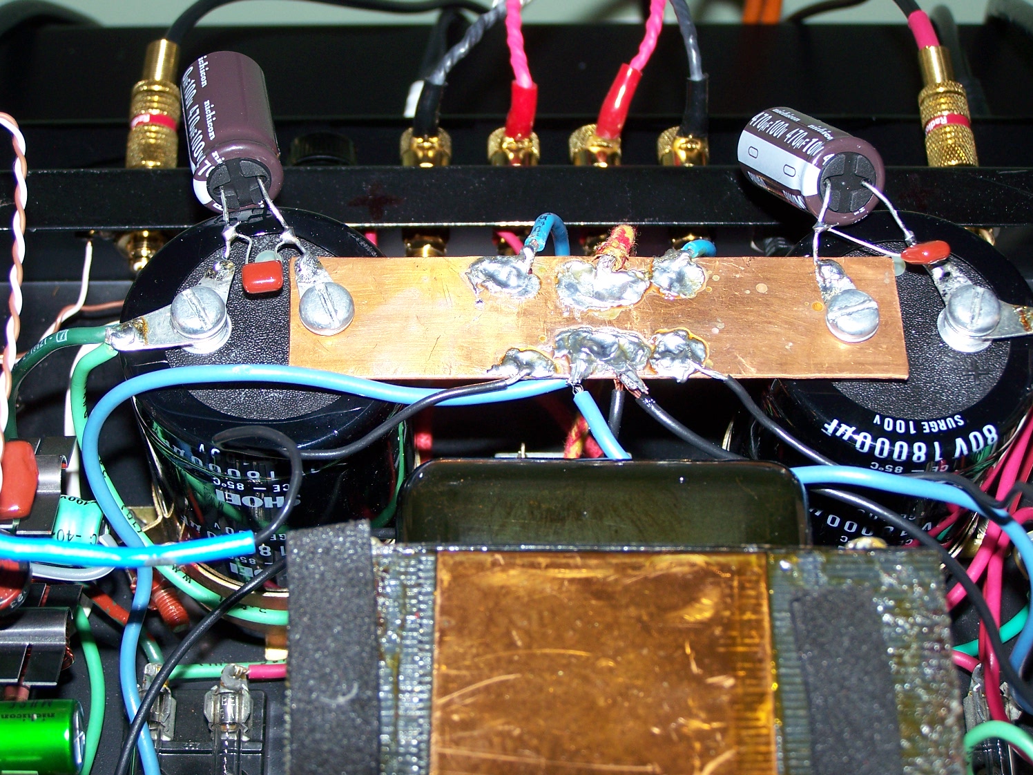
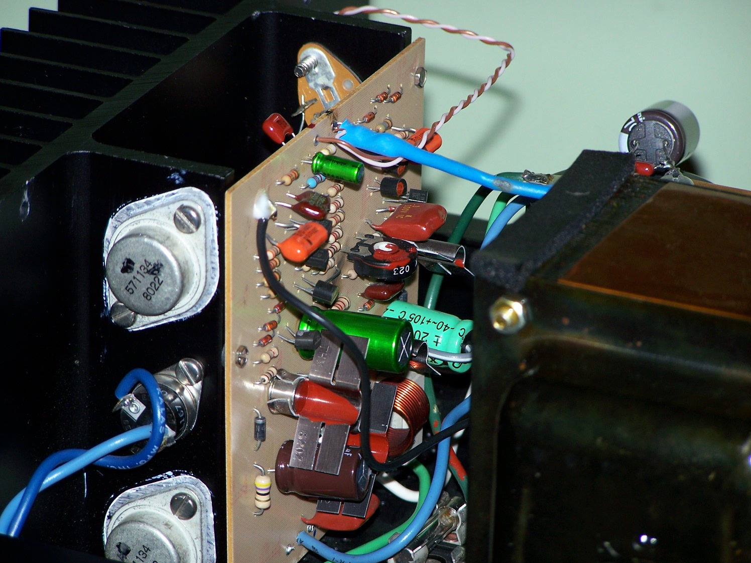
Here you can see output transistors black ground wire towards left side of pic. I drilled a hole and fed the film cap through it to meet the wire.
Here you can see the CAT 6 input wire and the main caps bypassed with a .1 uF film cap and a 470 uF 100V electrolytic. If someone has a good grasp of what these bypasses do, please say on. I have read Tamara's and Wong's white papers...

- Replaced all electrolytic capacitors.
- Mains were upgraded to 18,000 uF 80/100 VDC each caps (from 10,000 uF ea.)
- For bipolars, Nichicon MUSE ES were used
- For the other two, Nichicon and Xicon
- Installed 3 prong 14 awg power cord
- Grounded chassis
- Removed all grounds from chassis, ran them home via star topology to a replaced copper bus bar
- Input ground via 2.2 ohm resistors
- Replaced all input and outputs connectors with 24 K gold plated
- Used CAT6 data cable for input signals
- Bypassed all bipolar and main caps with .1 uF film caps
- Bypassed mains with 470 uF 100 VDC and .1 uF film caps
- Removed output tranny grounds, tied them to ground bus
- Installed an NTC 5 ohm thermistor as inrush current limiter
- Installed a class x capacitor accross the main AC line
- Set bias to 275 mA
- DC offset L 11 mV R 70 mV
Sound is awesome even with caps not broken in. Very quiet and powerful. Nice laid back disposition like that of tubes. Love it.
Thanks for all your help.
Here you can see output transistors black ground wire towards left side of pic. I drilled a hole and fed the film cap through it to meet the wire.
Here you can see the CAT 6 input wire and the main caps bypassed with a .1 uF film cap and a 470 uF 100V electrolytic. If someone has a good grasp of what these bypasses do, please say on. I have read Tamara's and Wong's white papers...
Attachments


What's been overlooked here so far is a very inexpensive and effective
improvement in the DH 200 (and DH 500) topology as suggested by Richard Marsh in a later Pooge article. You can cascode the input stage. You will need 4 more of each of the positive and negative input transistors, 8 of 10k 1/2 watt metal film resistors, and 4 of 10 uf 50 volts caps (63 volts for DH 500). It's a must to prepare the new transistor pairs BEFORE before trying to installing them on the board. Look at how the original input transistor pairs face each other - front to back on the pc board. Off the board place the new transistor pairs the same way and bend the base leads towards the front ( input) edge
audio.
of the pc boards and solder them together without cutting any of the excess lead off LeaUnsolder and lift the just the collector leads of the 2 transistors of each of the 2 input pair transistors. nextIt's much easIer to do the nAdd 2 more of the same device inserting their collector leads into the original trnsistors collector holes. Next attach the new tranistors emmitters to the original devices collectors.
What's been overlooked here so far is a very inexpensive and effective improvement in the DH 200 (and DH 500) topology as suggested by Richard Marsh in a later Pooge article. You can cascode the input stage. You will need 4 more of each of the positive and negative input transistors Q3,Q4 add 2 of 2N5550 as cascodes and for Q 5 and Q6 add 2 of 2N5401 as the cascodes , 8 of 10k 1/2 watt metal film resistors, and 4 of 10 uf 50 volt caps (63 volt for the DH 500). It's a must to prepare the new transistor pairs and resistors BEFORE before trying to installing them on the board. Look at how the original input transistor pairs face each other - front to back on the pc board. Off the board place the new transistor pairs the same way and bend the base leads towards each other and then solder them together. Then desolder and lift just the collector leads of the 2 original transistors off the board and point them up . Then insert the collectors of the cascode transistors into the orignal transistors collector hole and solder the collector leads. Next attach the new transistors emitters to the original devices collectors. you may want some extra devices to try this without soldering anything to see how how they fit and underatnd how they will all fit - it's a little tight and be carefull for shorts
To create a power supply for the cascodes solder 2 of the 10 K resistors in series - attach one end to the plus supply rail on the V + supply end of R9 on the component side of the board and the other end to ground at the pc wire lug 2 ( ground) - at the mid point between the 2 resistors solder the positive end of the 10 uf cap and ground the other end of the cap creating a filtered supply . Solder a lead from the resistors mid point connection and the cap over to the cascode's bases.
Insulate as needed - depending on your layout. Check you have about about half V + (30 VDC give or take a little) on the cascode's bases and 0.6 v less on the emitter of each cascode transistor when installed .
Repeat the 2 resistors + cap addition (reversing cap polarity) for the other differential using the V- supply side of R9 as the start point and ground as the termination .
Repeat for the second channel
That's it and check the offset it may need trimming -
Last edited:
What's been overlooked here so far is a very inexpensive and effective improvement in the DH 200 (and DH 500) topology as suggested by Richard Marsh in a later Pooge article. You can cascode the input stage...... -
Hi,
this seems really interesting, but, due to my less then perfect understanding of the english language, I've got lost following your description. I already have the TAA 4/1981 POOGE article but this mod is not included. Could you please send me a schematic or, even better, a copy of the relevant POOGE article?
Thank you,
Paolo
yes implimenting the cascoding is a little difficult to explain well in writiing - it is in a 1985 Audio Amatuer called Pooge 3 -Power amplifiers - I don't have a copy here to lift the drawing from - which showed the front end of any single or dual differential input power amp and how to apply the cascode
Last edited:
- Home
- Amplifiers
- Solid State
- Hafler DH-200/220 Mods