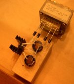
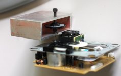
Erik van Voorst said:Top Picture...ready to be attached to the super regulator which we will leave in the close vicinity of the trichord 4 clock..
Hi Eric, what voltage do you get after the Diodes? I am still learning and have not seen this configuration before..
Attachments
ALWSR Regulator
Dear Erik van V
I look in the thread that you use ALWSR reg
and have great result
Were you change the caps and resistor or
you just use the original regulator parts ?
Can you give picture for AWLSR Regulator
Thankyou Erik
Erik van Voorst said:http://www.at-view.co.uk/alwsr.htm
Hello Stan I do not know if this is okay to mention but please moderator remove it if it is uncalled for...")
Andrew L. Weekes is the guys name..hence the company.....until James mentioned him I honestly never heard of him...
I am willing to try everything out because my present JVC/Sanyo set-up is still not in the league of the modded Wadia....
I must admit the blackgates are not mounted on de motorboard yet even as the mechanical construction...but they must be close to a miracle...
I will also try the 392/92 resistor combination....but as Peter advised I take my time after each change...
On the other hand there are a few tracks in which it most definitely already outperforms my Wadia...
So for me it is actually a thrilling process....
Dear Erik van V
I look in the thread that you use ALWSR reg
and have great result
Were you change the caps and resistor or
you just use the original regulator parts ?
Can you give picture for AWLSR Regulator
Thankyou Erik
As Anton mentioned...
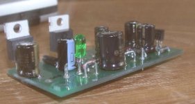
Today I found a bit of time after cleaning my small workshop to build a second "module" this time the pre-regulator for the super regulator who is taking care of the servoboard...
I have got the music on all day and I must say that one of the greatest aspects of supplying the clock is the feeling of "headroom" ...loads of air...and everynote out of the pitch darkness......I want more......lovely and very addictive...
BTW
I used the original super regulators...so far a 5V and a 12 V...
I just build the (pre)regulation with blackgate and schottky and LM78.......
More regulators to come for trying out...
Attachments
Erik,
did you try these modifications?
http://www.pinkfishmedia.net/forum/showthread.php?t=21574
Enrico
did you try these modifications?
http://www.pinkfishmedia.net/forum/showthread.php?t=21574
Enrico
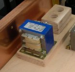
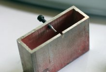
scrutinizer said:About 27 VDC.....We just use the "soldertags" to get a nice hardwired picture
Just for the looks.
Anton.
Hi Anton, why would you cut the second secondary? You could have run the secondaries in parallel or run 2 supplies from one transformer.
Attachments
Here's a simple tool I made in 5 minutes to remove the original disk table. I used scrap aluminum tubing and 8-32 screw with the end trimmed to 1.80mm diameter (mounted in a drill press and using disc sander). The tubing has 2mm slot cut out to accomodate motor shaft.
Attachments
I have just ordered all of my components from the US and fingers crossed they should be with me by the end of next week.
Can anyone recommend a supplier/part number for the regulator heatsink?
It would also be handy to purchase the 2x12v 100va EI transformer from the same supplier.
Thanks
Richard
Can anyone recommend a supplier/part number for the regulator heatsink?
It would also be handy to purchase the 2x12v 100va EI transformer from the same supplier.
Thanks
Richard
The original disc table that I received originally was seriously out of center, the new one seems fine but the hole is also a bit tighter. When you press it on, you might have problem removing it without damaging the shaft mount (the bearing plate tends to slide out when too much pull out force is applied). It's best to check the puck with disc mounted in drill press first, making sure it's properly centered. Otherwise your perfectly fine transport may become useless.
My new disc table has exactly 18mm height, IIRC, placing 1mm spacer on motor bearing should make it for the correct hight when fully pressed in.
My new disc table has exactly 18mm height, IIRC, placing 1mm spacer on motor bearing should make it for the correct hight when fully pressed in.
Hello Peter,
The dismounting tool is in my opinion the only proper way to go....your 1 mm spacer....you mean eg cut a 1mm ring in half place in in the vicinity of the 2 motor screws (I take it not on top of the screws) and then press the platform down and remove the spacer....
BTW I did not do the VBE mod...no time....and it takes also time to study a tweak .....and because it also takes a lot of listening per tweak.....sorry....
I think I am going fast enough...............
Erik van Voorst said:....your 1 mm spacer....you mean eg cut a 1mm ring in half place in in the vicinity of the 2 motor screws (I take it not on top) and then press the platform down and remove the spacer....
Yes, correct. It does not need to be a ring, just metal strip with a 2mm wide slot for the shaft, or maybe even two 1mm drill bits placed flat on both sides of the shaft.
To remove new table, one just needs to push a drill bit (less than 2mm in dia, mounted in a piece of wood) against the top of the shaft, pulling the table out.
I briefly checked new table, but it does not seem to be perfectly centered either (although it's not bad at all). I'm reluctant to test it in my current setup and need to temporarily assemble new transport first.
What do you think about this?
http://cgi.ebay.com/Spirit-Level-fo...47608412QQihZ020QQcategoryZ3272QQcmdZViewItem
From description hard to say it is clamp too or just level meter.
He sell real clamp for LP with build in spirit level and stroboscope too.
http://cgi.ebay.com/Spirit-Level-fo...47608412QQihZ020QQcategoryZ3272QQcmdZViewItem
From description hard to say it is clamp too or just level meter.
He sell real clamp for LP with build in spirit level and stroboscope too.
audio1st said:
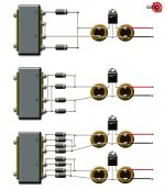
Hi Anton, why would you cut the second secondary? You could have run the secondaries in parallel or run 2 supplies from one transformer.
Hi audio1st,
Like the picture shows they where connected in parallel at first but after listening we had a 'feeling' that working with one secondary 'sounded' a little bit better.
I think for this kind of config I'll personely prefer a smaller transformer (about 24 VA) with single primary and secondary windings.
Anton.
Peter Daniel said:
I briefly checked new table, but it does not seem to be perfectly centered either (although it's not bad at all). I'm reluctant to test it in my current setup and need to temporarily assemble new transport first.
Oh man I was afraid of such a mail.. .
...now it maybe choosing between two evils...magnet or off-center...
I will wait and let you know as soon as my platform arrives...

- Home
- Source & Line
- Digital Source
- Finally, an affordable CD Transport: the Shigaclone story