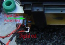
Dan_ed said:A little clarification please regarding digital output from the transport. I've read this thread at least 3 times but I'm still a bit confused.
I see from Peter's pictures that he took D-out from the opposite side of the pcb from where D-out is shown over by the TOC switch. I assume this is because of the hole that he drilled to get direct access to the pin. Are most folks using D-out for the location of the voltage divider?
See picture below...
Hi Erik, this is my second puck, same problem as you.
To fit it to shaft I just pushed it on by hand. Just measure distance from CD face to deck of original. About 19 mm worked for me..
Attachments
Thanks..
I used the drill chuck ...I got the idea of applying (to) much presure ...also removing the old platform needed a lot of force so I used a small cutting wheel for that in the end...
I am also very curious if it is at all comfortable in usage...since you have to press the cd down in order to screw it on....and feel if it is okay....
audio1st said:
See picture below...
Hi Erik, this is my second puck, same problem as you.
To fit it to shaft I just pushed it on by hand. Just measure distance from CD face to deck of original. About 19 mm worked for me..
Me too, new puck is on the way.. Keeping my fingers crossed.
cd clamp off center
based on a recent conversation with the university machine shop manger i am not surprised that some cd clamps are turning up off center. i had the same problem with mine.
the issue is that the tool used to make the hole (drill bit or reamer) is not stiff enough to run straight for such a long distance. the further it has to travel the further off center it moves.
to avoid this problem i am going to modify the original design so that only the first quarter inch or so of the clamp contacts the motor shaft.
it is likely that all the clamps are off center as a result of this issue, however, the offset may not be significant in some cases.
it might be possible to save some of the clamps by boring a larger hole (so that it no longer contacts the shaft) at the end opposite to where the hole was initiated.
The way to solve this right is not to shorten the bore, but to actually bore it with a boring bar. A drill or reamer will wander. A boring bar will not. To get it nuts on, use the boring bar to get within a couple thousandths and then run a reamer the hole. The reamer will always follow the hole, and with a bored hole, it will be straight. Anything else will only be making it better, but not really doing it right.
Just my 2 cents. I had this part all planned out, but our shop is too busy.
Just my 2 cents. I had this part all planned out, but our shop is too busy.
 Just a note for anyone waiting on a replacement clamp..Do not lose or damage your original screw on puck, it is not supplied with the new base.
Erik van Voorst said:
I am also very curious if it is at all comfortable in usage...since you have to press the cd down in order to screw it on....and feel if it is okay....
Hi Erik, Yes it is a bit fiddly to use, I'm sure you will design a friction brake for the shaft, which could be released via a solenoid, operated by the TOC/eject switch.
")
hi dave,
where can i get a boring bar for a 2mm hole?
edit: that can go to a depth of 20 mm?
Here you go.
http://www1.mscdirect.com/CGI/NNSRIT?PMPXNO=1685755&PMT4NO=47264878
Setup will be a pain in the back side, but it should get you there . I would pre drill with a .065 drill and then bore it out. You shouldn't need a reamer, but if needed, finish the hole with a reamer.
Hope that helps.
okapi said:hi dave,
where can i get a boring bar for a 2mm hole?
edit: that can go to a depth of 20 mm?
Hi Okapi,
there are some german companies who have boring bars beginning at 0,3 mm...
For example:
SIMTEK
Maybe you can get something similar in the US.
Greetings
Markus
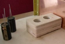
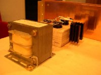
Today we finished the power supply for the trichord 4 in combination with its own 12 V Super Regulator....
In my set-up and in my perception ...It is a clear winner...
First Impression a lot more ambiance/air and more colour on the instruments...to tired so I go to bed...but very re-assuring that it immediately works out for the clock to have a dedicated advanced power supply...
The foto shows a baltic birch block to keep my elco's quiet...
Attachments
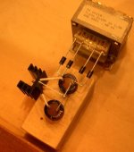

Tham said:For convenience, I have connected the LED back light with a resistor in series by tapping to the same 8v regulate supply instead of after the rectifier as suggested. Will this in anyway affect sonic?
It may or may not, try both ways and see if you can hear the difference
Personally I'm not really picky in those matters, but having choice before, or after regulator, I choose the first option.
- Home
- Source & Line
- Digital Source
- Finally, an affordable CD Transport: the Shigaclone story