Well now I am on holidays over XMAS I got the time to really put in a solid chunk of time on the DDS based synthesiser.
Previous blog entries describe the PIC32MX based core to this. The thing works like a charm...
To get decent precision on the sinewave I have implemented an interpolation on a high precision Sinewave lookup table.
- The DDS references into a 12 bit "long", 24 bit "amplitude" precision sinewave LUT.
- Of itself this gives mediocre spurs, which in a DDS are heavily dependent on the frequency, but seem to result in 85-90dBc spurs. There is a fair hash of these without treatment.
- By adding a linear interpolation between samples in the Sinewave Lookup table, the spurs come out as shown below...
- The interpolation is actually quite simple in concept:
- The top 12 bits of the DDS Phase Accumulator looks up the "Sine Sample" ...
Posted 18th December 2013 at 10:35 AM bygooglyone Updated 18th December 2013 at 10:38 AM bygooglyone
Over the last couple of months I have been playing with a PIC32MX450F256H as the DDS core, and using one of the many DAC boards I built for my DSP based crossover as the D/A element.
It has taken a while to get up and running - mainly due to me actually having commitments other than a hobby... (Bugger)
That said, getting this thing up and running also required me to get my head around the microchip XC32 compiler, and the configuration bits in the PIC32MX.
On the compiler, the most serious issue is the schemozzle they call documentation. I imagine if all you wanted to do was simple I/O and stuff you might be OK. As soon as you want to dig into the more detailed registers, the high level library documentation is borderline useless, and spread over a number of directories and the Microchip website. Very frustrating.
The other challenges I had were:
- To set up the PIC I2S interface such that there was no jitter on the LRCLK...
Posted 3rd November 2013 at 03:29 AM bygooglyone Updated 3rd November 2013 at 03:31 AM bygooglyone
I noted that the new PIC32 series micro controllers include I2S along with the SPI interface. Well at least a few in the range do. This got me to thinking:
- A 32 bit micro using a fairly efficient RISC architecture
- With I2S in and out
- That runs at 80MHz.
I chose the PIC32MX450F256H.
Surely to god I can do something fun with this. But what?
Ultimately I will try chucking some IIR filters in here to see how they go (there is heaps of processing time available). But in the first instance I want to do a DDS. Reason being that I have more active crossovers than I have speakers (and that is saying something! - ask my long suffering wife!).
One thing that I have been on the look out for is a decent DDS synthesister for audio band that has really low distortion. My current Audio synthesiser uses the AD9952 DDS chip. OK, this runs at 400MHz, but it does use a 14bit DAC, and can be run right down into the...
I got a question or two on doping of speaker surrounds.
Here is the thing: If you buy an OEM cone kit it will either come with a pre-doped surround, or be provided with the doping material and instructions.
I have reconed a lot of drivers and until recently either used OEM kits or kits from providers who have looked after this for me.
A good example of a provider that gave doping compound was BEYMA. The instructions etc for this were idiot proof, and the material nicely packed in the kit.
To apply this I used a stiff "cleaning brush" as you would but from your local hardware store - a steel handle about 100mm (4") long crimped onto stiff bristles. Worked a treat.
The beyma doping material looked and smelt for the world like really thick PVA glue. The difference was that when dry it did not go that hard, and remained almost but not quite tacky.
Well, you learn something every day. I suppose if you don't manage to learn as you go, then you probably stuff things up every day!!!
About 12 months ago I came across some RCF L18/551 eighteen inch subwoofer baskets. I reconed them using aftermarket parts, the process went OK but I was kind of bemused by the untreated cloth surrounds.
I was busy, and had no immediate plans so the drivers were shelved for a rainy day.
The Thielie and Small parameters were "OK" but not exact as OEM. I measured these using the addded mass method, an important fact for later. As an aside, they would do well enough as subs, but their Fs was a bit higher than I would have hoped.
Fast forward to last week, I loaded one into a 220 litre box tuned to 34Hz, and measured the impedance.
Bugger me if the resonance showed one massive peak at pretty much the driver Fs, and a tiny lump out at 80Hz. Huh?
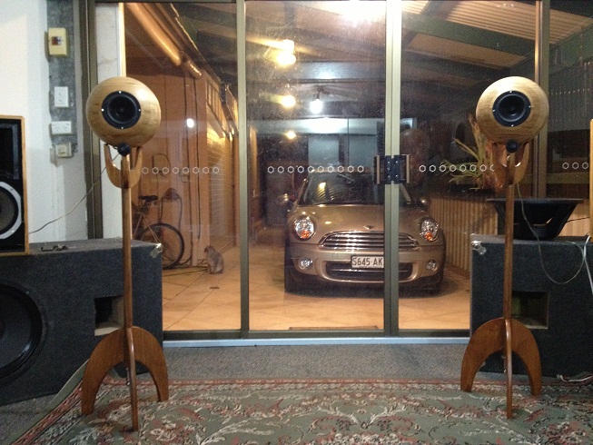
I stumbled on the people making speakers from the Ikea bowls. It kind of inspired me as the speakers were truly different and bizarre, but at the same time something completely different.
So I had to make some.
I fumbled around in the cupboard and came up with three choices of woofers that would do OK in a small enclosure - and after a few measurements and stuff settled on a pair of old Vifa M13SG-09-16 drivers. These were pretty well suited to an enclosure of a bit over 8 litres.
This drove me to the larger bowl, a 28cm one.
This is how they came out...
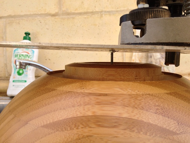
To fit the driver I simply routed a rebate - and then cut the inside out.
The material of the bowl was quite thin once I had finished routing things - so I cut out a circle of ply and glued it to the inside of the bowl. I had to go out for the evening at that point so I simply...
Posted 20th November 2012 at 12:55 PM bygooglyone Updated 20th November 2012 at 01:02 PM bygooglyone
I have had a few people ask for the CAD files and software for the ADAU1442 DSP. I have tried uploading the whole lot as a series of ZIP files - I hope this works OK.
There are a few things that warrant comment, and if you try to untangle this lot, I am sure a few questions to me. Feel free to ask away...
Comments:
- The sigmastudio file is simply there to generate the code for the DSP. All the actual values for filters etc are calculated by the microcontroller under user control.
- SigmaStdio generates a bunch of export files, my software uses the *.h files, both to load the DSP code, and also to get the addresses in the ADAU1442 of registers for biquad coefficients etc. The microcontroller code pretty well loads these in straight, but there is a tiny bit of tidying up the sigma generated files first...
- The microcontroller is a PIC18F4560 (from memory) the CAD file has a PIC18F5420 in the schematic - these are pin...
Posted 2nd September 2012 at 08:11 AM bygooglyone Updated 15th September 2012 at 08:10 AM bygooglyone
Wow - it has taken me months to finally get around to packaging up my latest DSP. With work, travel and holidays I have a huge bag of excuses, but I guess the actual reason is that my old DSP using the Analog Devices AD1940 actually works just fine.
The results are I think pretty neat:
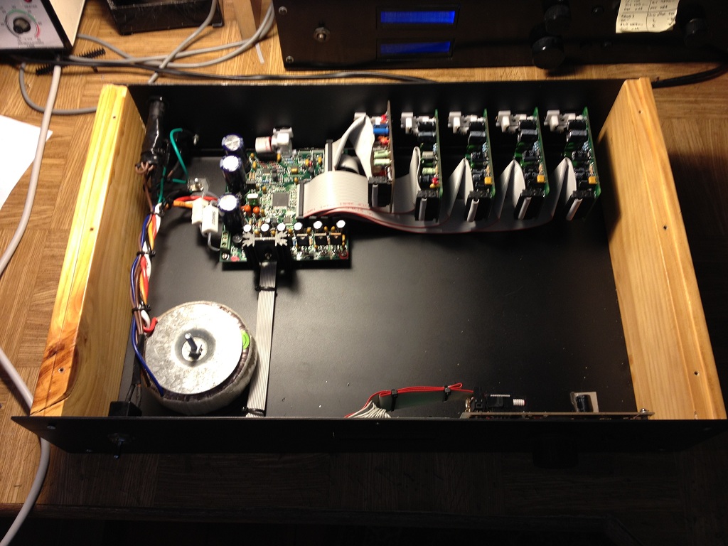
The case was made from leftover bits from the last set I built - the sides are simply timber with a groove routed for the top and bottom panels to sit in, and the front and rear panels screw into the timber sides. It makes a change from the multitude of "all metal" cases that litter my workroom and playroom.
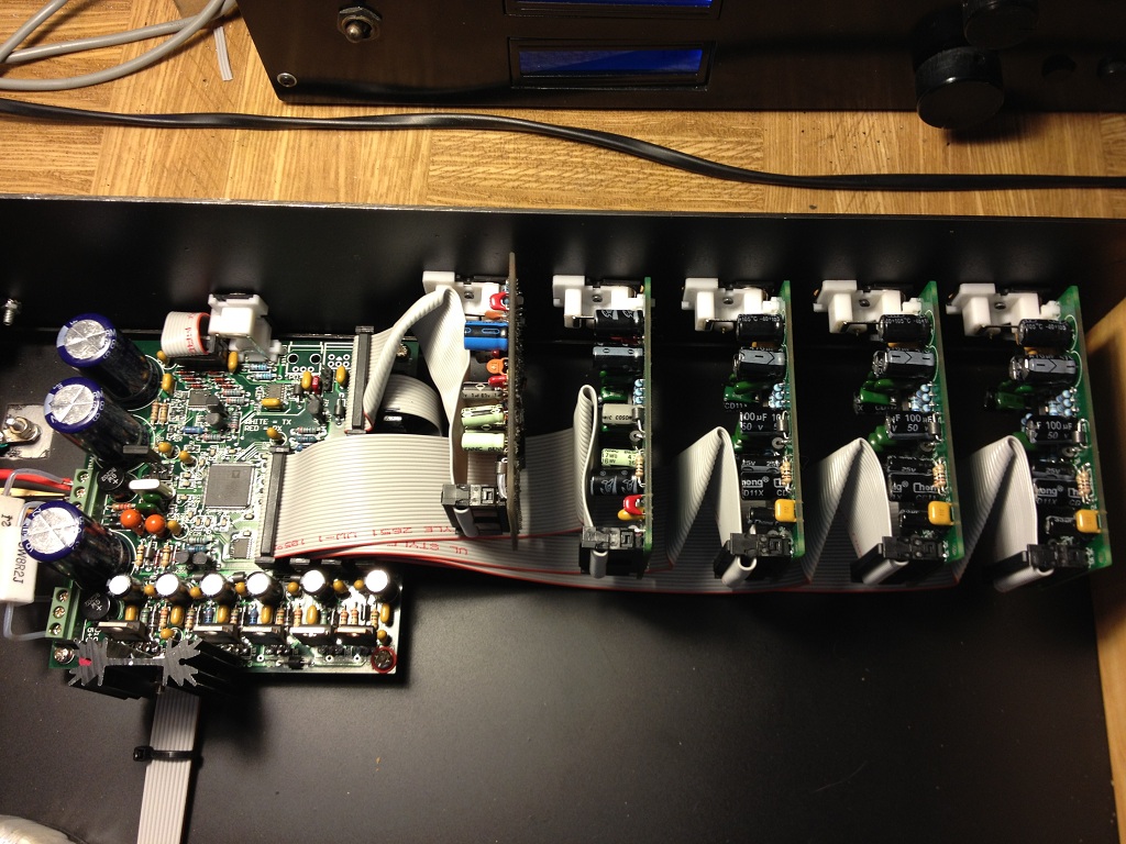
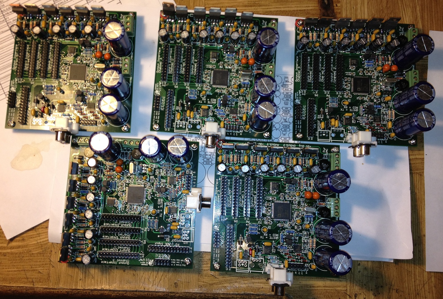
The implementation here has one analogue to digital converter and four digital to analogue converter cards.
These can be seen here:
Where the ADC is the first vertically mounted bard on the left with the slightly scruffy IDC cable. The four DACS...
I got to the point with my new audio DSP / crossover that I had no more excuse not to load the remaining PCB's I had manufactured.
I initially only loaded one of them, on the basis that if I had a clanger in the layout I could get a new spin of the boards.
Well the thing is all working and I have updated the DAC board - so the remaining five boards needed loading. I find a bit of PCB manufacture and loading to be quite therapuetic - as my previous blog entries will show.
This weekend I found my limit - loading the SMD's for these five boards - by hand in my toaster oven - took about three hours, then loading all the through hole parts, particularly headers and power supply parts blew away I would guess six more hours. I am over it!!!!
They do look pretty though!
The only part remainig to be loaded on these boards is the ADAU1442 regulstor transistor. Thay will allow me to...
One thing that always used to give me grief at home was loading fine pitch surface mount IC's.
I recently bought a toaster oven having read several people's experience using these to relow SMD's.
I lashed out and bought the el-expensivo fan forced model, as this was in one forum reported to give more even heat. After some playing around I concluded the oven would actually be really very good.
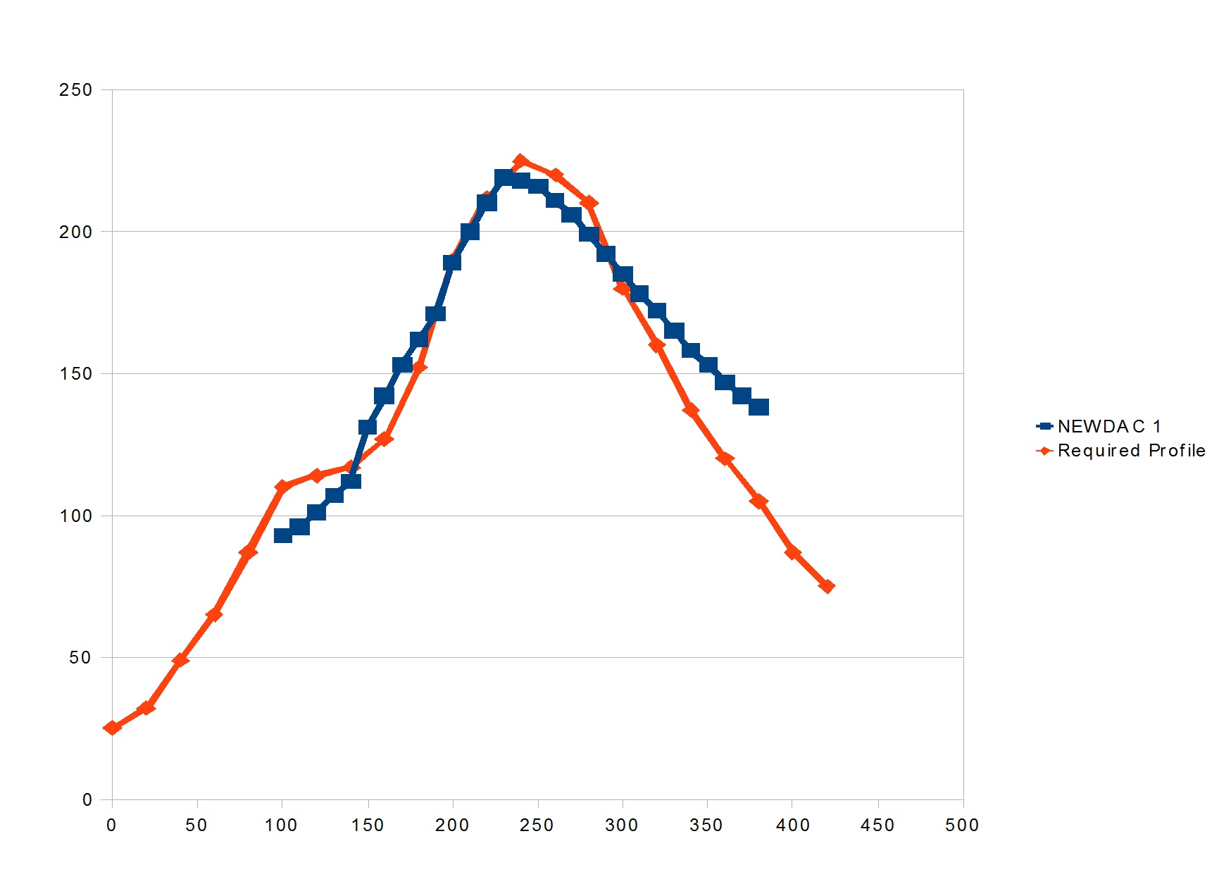
I found that if I did the following (with my oven):
- Turn on and run on 2 bars until temperature = 100C,
- Turn down to one bar, and run for 60 seconds,
- Turn on two bars and continue until the temperature is 210C,
- Turn all bars off, leave fan on and open the door a crack.
The heat continues to increase to about 220, and the profile is really very close to many manufacturers recommended profiles.
I don't use silksceeens, I use a syringe and put a very little...