The Amanero is connected with an external 3.3V psu, but there is no sound. I am sure that the connections are ok.
I guess that this is due to the fact that the display is not connected. It must be necessary to use the input selector of the display. Can anyone confirm please?
There are two output 5V pins in J9. Are they there for a specific reason?
I guess that this is due to the fact that the display is not connected. It must be necessary to use the input selector of the display. Can anyone confirm please?
There are two output 5V pins in J9. Are they there for a specific reason?
Last edited:
So, you are connecting an Amanero to the second i2s port in order to compare it to the onboard xmos, right?
What firmware version is your board? The early firmware release did not enable the i2s port and you will need to update. The display has likely nothing to do with it as the default setting of the board is for automatic scanning of the inputs. Unless you have changed this the active input should be automatically selected.
What firmware version is your board? The early firmware release did not enable the i2s port and you will need to update. The display has likely nothing to do with it as the default setting of the board is for automatic scanning of the inputs. Unless you have changed this the active input should be automatically selected.
So, you are connecting an Amanero to the second i2s port in order to compare it to the onboard xmos, right?
Yes.
What firmware version is your board? The early firmware release did not enable the i2s port and you will need to update. The display has likely nothing to do with it as the default setting of the board is for automatic scanning of the inputs. Unless you have changed this the active input should be automatically selected.
I bought this board may be 6 weeks ago. I understant that the active input should be automatically selected. How can I update it, if it is what I should do?
Check the firmware version and update if not the latest. The procedure of updating via a terminal program and a serial port is described in the manual.
Ok, I will read it carefully and try to it myself. If I can't do it, I have a friend who can. Thanks!
hello, is there a 1941 board owner willingly to make some tests and post them on forum?
dam1121 fpga changes the frequency of si5xx to keep fifo functional once per 1ms.
I'm curious to know if dam1941 will make the same when useing the xmos input. Theroretically if fpga and xmos run sync, those changes in frequency would't be necessary, but who knows?
So, anybody having 1941, a cheap logic analizer to log the i2c and some time? I will give the beer!
https://www.diyaudio.com/forums/ven...magnitude-24-bit-384-khz-284.html#post5902669
post #8515
For DAM boards with on-board USB, no clock adjustments Sören says.
//
post #8515
For DAM boards with on-board USB, no clock adjustments Sören says.
//
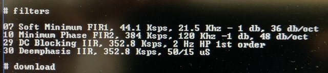
Stock filters?
//
I recently downloaded Spikestabber's filter package 1.21 and used it on a DAC for awhile, but somehow I couldn’t get used to the new sounds. My preference was F6 Minimum (green LED) as most listenable from the pack, but I couldn’t get rid of sensation that the sounds were somehow manipulated to create pleasing effect. The raw energy was missing and after a while it felt a bit boring. F4 and F5 I didn’t care at all and F7, which was my preference with stock Soekris filters, felt dry.
I was kinda disappointed with all that new filters experience and went back to what I’ve been listening most of this year: minimum phase (LED off), stock filter. To me, it sounds just right: no “special effects”, very simple and pure, preserving that special something that makes the music “touch you”.
I will certainly go back again to testing those filters, but for now I don’t feel much tempted.
I loaded them today and was nicely surprised. The F5 (red LED) sounded very interesting and certainly better than Soren’s version. I had hard time deciding if I like NOS or yours better. I still think that NOS sounds more natural with better definition of bottom end but need to listen more.
C128dp sounds very nice too, but to me a bit too nice, not very natural.
C128dp sounds very nice too, but to me a bit too nice, not very natural.
So far, the F5 filter (EQHQ_lpbr_b4 Linear Phase filter) of the Party pack (or TNT file) is still my favorite, though I also use the TNT F4 regularly. I think F4 sounds a bit more clean & has better imaging. Though I feel it is also somewhat less lively. F5 sounds more dynamic & lively (and louder, which has such an effect as well).
Fedde
Fedde
and F7, which was my preference with stock Soekris filters, felt dry.
Hm. I thought there was basically one single version of the NOS filter in all the packs. And the Spikestabber pack was only adjusted for gain. Was I wrong?
How does accuracy of this DAC resistor ladder compare to older R2R chip like PCM1704?
In what way is the soekris ''27 bits'' and a PCM1704 ''24 bits''?
you can visibly see the ladder consists of 27 groups of resistors but surely the DAC cant actually resolve 27 bits and if it could there wouldnt be any 27 bit data to send it, so what is reason behind it?
I can understand the PCM1704 could handle 24bit input natively without need for dithering, but that is hardly enough to explain why they designed the DAC to be 24 bit.
Also how does the resistor tolerance factor into this, you could build 27 bit resistor ladder with 5% or impossibly high tolerance 0.0001% resistor. I think I have seen mentioned 0.01% is not ''enough'' for 24 bit (possibly ignoring other factors).
Last edited:
- Home
- Vendor's Bazaar
- dam1941 - Next Gen Discrete R-2R Sign Magnitude 24 bit 384 Khz DAC module