Classic LM3886 (a.k.a. ChipAmp, GainClone; 45 W, 8 Ω, <0.002% THD+N) Boards and Kits
For sale are boards and kits to build an LM3886 power amplifier and its power supply.
The boards are classic in the sense they are compact (same size as the BrianGT boards) and are easy to build with a simple schematic, low part count and an easy layout. At the same time, compared to BrianGT's and most other boards on the market today, they offer improved distortion performance - less than 0.002% THD+N at 45 W into 8 Ω from an unregulated power supply, with excellent high frequency linearity and power supply rejection - due to advanced signal routing.
The kits offered here include the boards described above and a full complement of board mounted parts and are intended to make it a simple, enjoyable build. You would need to add power transformers, heatsink(s) and perhaps an enclosure with some connectors to make it a fully functional power amplifier. Unless you intend to use it with a preamplifier, you would also want a suitable volume control and, optionally, an input selector.
To purchase, please visit hifiocean.com.
Thank you!
For sale are boards and kits to build an LM3886 power amplifier and its power supply.
The boards are classic in the sense they are compact (same size as the BrianGT boards) and are easy to build with a simple schematic, low part count and an easy layout. At the same time, compared to BrianGT's and most other boards on the market today, they offer improved distortion performance - less than 0.002% THD+N at 45 W into 8 Ω from an unregulated power supply, with excellent high frequency linearity and power supply rejection - due to advanced signal routing.
The kits offered here include the boards described above and a full complement of board mounted parts and are intended to make it a simple, enjoyable build. You would need to add power transformers, heatsink(s) and perhaps an enclosure with some connectors to make it a fully functional power amplifier. Unless you intend to use it with a preamplifier, you would also want a suitable volume control and, optionally, an input selector.
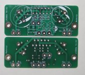
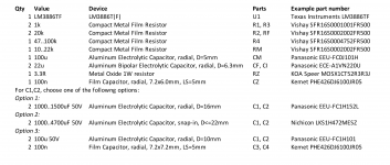
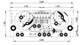
- Classic LM3886 Amplifier PCBs (pair). Compact (2.9 x 1.2 inch each), simple (only 14 parts per channel), high performance (<0.002% THD+N at 45 W into 8 Ω). $9 per pair of PCBs. Note: a power supply with isolated rails is recommended for best distortion performance; separate power supplies for each channel (a.k.a. dual mono) are also recommended for low noise. A suitable power supply can be built with Power Supply PCBs or Kits listed below.
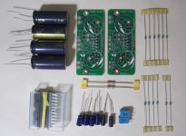
- Classic LM3886 Amplifier Kit (two channels). A pair of boards as above plus a full complement of components, except the heatsink(s) and connectors. $49 per stereo power amplifier kit.
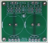
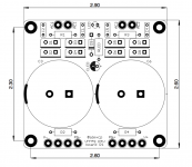
- Classic Power Supply PCB. 2.6 x 2.9 inch, with two isolated rails. CRC snubbers for each secondary winding damp the ringing of the transformer's parasitic inductance and capacitance. A separate rectifier for a LED power-on indicator is included on the board and allows the LED to switch off quickly when you turn off the amplifier. Requires a transformer with two isolated secondary winding; one center tapped winding won't work. $9 per PCB. Note: two PCBs and two transformers for a stereo amplifier (i.e. one per channel) are recommended.
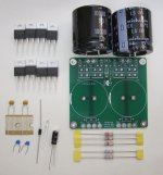
- Classic Power Supply Kit. One board as above plus a full complement of components, except the power transformer and its associated primary side (mains) circuitry. Requires a transformer with two 18VAC..24VAC isolated secondary windings; one center tapped winding won't work. $29 per kit. Note: two Kits and two transformers for a stereo amplifier (i.e. one per channel) are recommended.
To purchase, please visit hifiocean.com.
Thank you!
Attachments
Last edited:
Classic LM3886 Amplifier PCBs
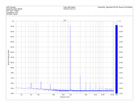
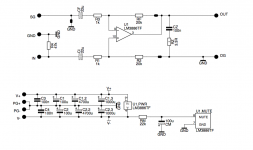
Attached are the schematic, mechanical details and component placement, a sample BOM for one channel, the spectrum of 1kHz sine wave driven by the board at 45W into a 8Ω load with an unregulated power supply, and a photo of the sample build as tested. The BOM is also shared via the Project Manager at Mouser.
Some notes:
- The board needs two 25..35v power supply rails. They do not need to be regulated. Higher voltages increase output power but also increase dissipation, esp. for 4Ω loads; refer to the LM3886 datasheet for details. The absolute maximum power supply voltage that an LM3886 can withstand with the input signal applied is 2x42V.
- The board shows its best distortion performance if powered by two isolated power supply rails connected to (V+, PG+) and (V-, PG-). A bipolar power supply with one common connection shared by the two rails (e.g. V+, COM, V-) will work, but the distortion will be higher.
- In a stereo setup, separate power supplies for each channel are recommended. The reason is that, as in most LM3886 based designs, the input signal is referenced to the board's local ground. In a stereo amplifier powered from a single power supply, the local grounds for each channel will inevitably be slightly different. The difference will add to the input signal, resulting in additional noise and distortion. With the distortion as low as this board can produce, it doesn't take much difference to ruin it; 0.002% of 1V(rms) input signal if just 20uV(rms). Separate power supplies for each channel solve this problem. A possible workaround (not a solution) with one power supply shared by two channels is to connect the local grounds of the channels with a short, thick wire with low impedance and hence low voltage drop.
Attachments

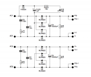
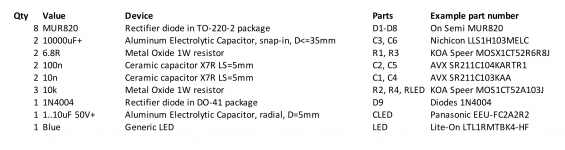
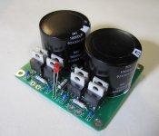
Classic Power Supply PCB
Attached are the schematic, mechanical details and component placement, a sample BOM for one channel, and a photo of the sample build as tested. The BOM is also shared via the Project Manager at Mouser.
As noted above, the board required a power transformer with isolated secondary winding. A single winding with a center tap won't work.
Attachments
Hi Alex,
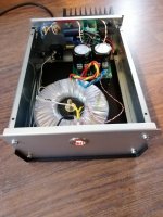
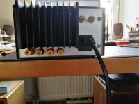
Today I have finished the amp. There is no audible hum and the offset with capicitors omitted is 30 respectively 39mV. In the Netherland we don't have wall outlet with ground in the living room, so groundloops are not a great problem. The sensitivity is 4dB lower than Brian's amps, but that is not a problem in an active system. I am very content with the Amp. Thank you.
Best regards, Cornelis
Attachments
Congrats, Cornelis!! Yours is a very nice build indeed. Enjoy the music!
Is this a modushop.biz (aka HiFi2000) enclosure?
Is this a modushop.biz (aka HiFi2000) enclosure?
Last edited:
Hi Alex,
The enclosure is a cheap one: MODU Economica 1EP1001825, cabinet, 180x250x100mm.€ 21, 40.
The enclosure is a cheap one: MODU Economica 1EP1001825, cabinet, 180x250x100mm.€ 21, 40.
Do you have the THD vs frequency graph as well? I often find that to be a better indicator of the layout quality than the 1 kHz spot measurement. Even if you can't get your test equipment to do the sweep for you, it's pretty easy to measure three points per decade in a logarithmic sequence (10, 20, 50, 100, 200 ...) IMD (multi-tone and 18+19 kHz, 1+5.5 kHz) can be a good indicator as well.
Tom
Tom
I don't own such equipment. You can ask Alex for measurements . I drive a pair of tweeters with the amp. They are very adequate for the job.
Do you have the THD vs frequency graph as well? I often find that to be a better indicator of the layout quality than the 1 kHz spot measurement. Even if you can't get your test equipment to do the sweep for you, it's pretty easy to measure three points per decade in a logarithmic sequence (10, 20, 50, 100, 200 ...) IMD (multi-tone and 18+19 kHz, 1+5.5 kHz) can be a good indicator as well.
Tom
Hi Tom,
Thank you for your continuing interest. Too bad I missed the Burning Amp festival this year - I heard you presented there your composite amps?
I totally agree with the point you're making - THD @ 1kHz can give pretty numbers but does not necessarily tell the full story.
Attached to the post #26 in the other thread is the result of testing with the 19+20kHz dual tone at full power, which gives some idea of HF linearity.
BTW, you do your measurements with an AP rig - do you own one?
BTW, you do your measurements with an AP rig - do you own one?
Yep. I own and use an APx525. Best investment ever!
Tom
Boards and kits to build an LM3886 power amplifier and its power supply, as well as some other goodies, are now available at hifiocean.com.
A/B chip amps are a typical starter drug, was my first in the 70th.
The nice thing is you can still understand what you do, even better than with discrete amps, that need some in deep understanding.
With D-amps and SMPS "know what you do" is not really the case. One wrong move and anything goes "Bang".
The nice thing is you can still understand what you do, even better than with discrete amps, that need some in deep understanding.
With D-amps and SMPS "know what you do" is not really the case. One wrong move and anything goes "Bang".
Example transformer for your PS boards?
@alexcp,
Can you provide a link or recommendation for a suitable transformer for your Power Supply boards?
Would this be a suitable candidate? Avel Lindberg Y236652 250VA 25V+25V Toroidal Transformer
I will be using it to power a set of your LM3886 boards that will be driving a set of Baby Avent III's (8 ohm nom) for office use.
Thanks,
Bryan
Avel Lindberg Y236652 is not a bad, if somewhat oversized, choice for a stereo amplifier. For office use, I would go for a 100-160VA 20+20, 22+22 or 24V+24V transformer, such as Avel Lindberg Y236503 160VA 22V+22V, Antek AN-1222 or Triad VPT48-2080.
By the way, Tom Christiansen did all the number crunching on power transformers for LM3886 to make an informed decision on what kind of transformer is sufficient. Have a look at his web site.
By the way, Tom Christiansen did all the number crunching on power transformers for LM3886 to make an informed decision on what kind of transformer is sufficient. Have a look at his web site.

The LM3886 boards are back in stock.Hi Alex, any idea when these might be back in stock? Thanks!!
- Home
- Vendor's Bazaar
- Classic LM3886 (a.k.a. ChipAmp, GainClone; 45W, 8Ω, <0.002% THD+N) Boards and Kits