I can't imagine there won't be license fees. And cost for certification. I believe that's reason for the existence of MQA. Doubtful that it would be just a library available. There's all kinds of debate on various forums.If you have to pay a license fee to use it then I don't think you will see to many takers for it considering that it is just going to chew up more DSP resources which could otherwise be used for other purposes. If there is a MQA code library available for SHARC DSP's then it may be worth looking at but if it is anything like Dolby or HDMI licensing I think I will pass on that.
cheers
Personally, I hope it goes down in flames because, I believe it's success depends on whether it takes over the entire market or not. And that would be bad for innovation.
Sent from my XT1528 using Tapatalk
I can't imagine there won't be license fees. And cost for certification. I believe that's reason for the existence of MQA. Doubtful that it would be just a library available. There's all kinds of debate on various forums.
Personally, I hope it goes down in flames because, I believe it's success depends on whether it takes over the entire market or not. And that would be bad for innovation.
Sent from my XT1528 using Tapatalk
+1
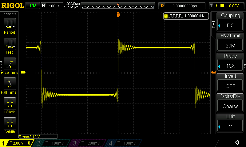
Thought people maybe interested in the Squarewave Response of the 7 built in FIR filters of the Sabre ES9028PRO DAC.
1. Fast Linear-Phase

2. Slow Linear-Phase
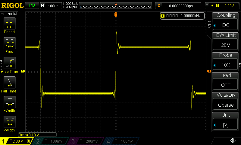
3. Fast Min-Phase
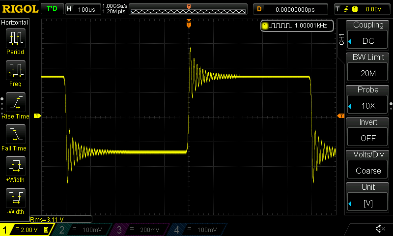
4. Slow Min-Phase

5. Apodizing Linear-Phase

6. Hybrid Min-Phase
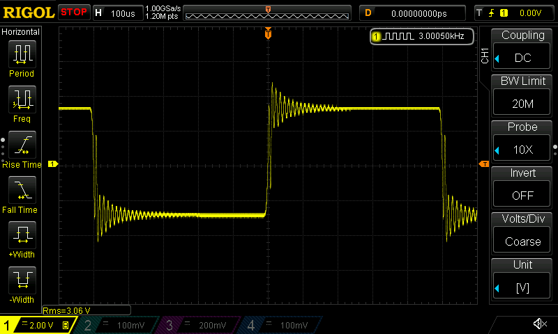
7. Brickwall
1. Fast Linear-Phase
2. Slow Linear-Phase
3. Fast Min-Phase
4. Slow Min-Phase
5. Apodizing Linear-Phase
6. Hybrid Min-Phase
7. Brickwall
Hmm, so no totally symmetrical version. I suppose it is not only the ESS that is shown? Is this in your application?
//
//
Hmm, so no totally symmetrical version. I suppose it is not only the ESS that is shown? Is this in your application?
//
No it's a 1KHz square wave generated by the DSP piped directly into the DAC.
Of course there is still the ability to customize a filter 😉
cheers
No it's a 1KHz square wave generated by the DSP piped directly into the DAC.
Of course there is still the ability to customize a filter 😉
cheers
Is it at 44.1KHz? Does it look the same at 96KHz?
Other filters is an attractive idea...
Is it at 44.1KHz? Does it look the same at 96KHz?
Other filters is an attractive idea...
Sorry I should have said that it's at 192KHz 😉
cheers
The ringing is near the Nyquist frequency at 96k.
Why is this a problem?
Other than that the analog stage has to cope with the overshoot without clipping.
Why is this a problem?
Other than that the analog stage has to cope with the overshoot without clipping.
Interesting to see the effect of the time delay in the FIR filter, which causes some of the filters to start vining before the signal transition...quasi non-causal...but for the overall time delay.
I am surprised to see so much ringing. e.g fast and hybrid min-phase. How many taps are you using in these filters? And, do they all use the same tap count? Seems like a higher tap count would reduce the ringing at the transitions. If they are all the same, then obviously some filter types are more or less sensitive to this.
Scott
Whether you are testing at 96khz or 192khz you will always see some of what you are calling ringing as determined by any brick wall filtering or band limiting, this does not mean that there is any real ringing going on, just a by product of a band limit. This is a deceptive result we are seeing here without all the facts of the test.
Is't it just a tradeoff to get sharp filters with low latency. Then ringing must be accepted. And the ringing is far above hearing frequencies. If this sounds bad, all metal domes (resonance above 20k Hz) sound bad.
An the ringing starts in the 0.1 ms region before the square wave. Human threshold is in the 1 ms region. Google Haas effect. (And that is signals in the audible spectrum)
An the ringing starts in the 0.1 ms region before the square wave. Human threshold is in the 1 ms region. Google Haas effect. (And that is signals in the audible spectrum)
I am not so sure it is deceptive.
The ringing may be caused by a number of things.
Fist, there is an analog filter after the DAC (one would assume), and this presumably has a cutoff around 96 KHz. That might cause the trailing edge ringing (since it is causal), but it would presumably cause the same ringing for every filter type.
Second is ringing caused by an incomplete waveform composition. If you create a square wave with a Fourier series you can see that it starts out as a sine wave and as you add components (additional sine waves of different amplitudes and frequencies) the ringing (sometimes called "ears" ) appear at the transitions. Here is an example.
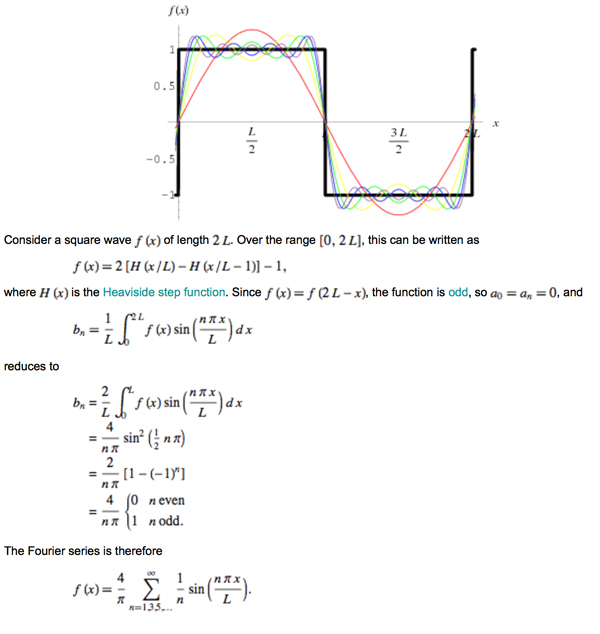
As the number of components increase to infinity, the frequency of these ears increases, eventually becoming infinitely high. As noted by Kindhornman, if the system is band limited (which we know it is, since it is sampled at 192 KHz, resulting in a max frequency of 96 KHz), then you will be stuck with some amount of ringing.
It would be very interesting to see how this looks with a 20 KHz square wave.
The ringing may be caused by a number of things.
Fist, there is an analog filter after the DAC (one would assume), and this presumably has a cutoff around 96 KHz. That might cause the trailing edge ringing (since it is causal), but it would presumably cause the same ringing for every filter type.
Second is ringing caused by an incomplete waveform composition. If you create a square wave with a Fourier series you can see that it starts out as a sine wave and as you add components (additional sine waves of different amplitudes and frequencies) the ringing (sometimes called "ears" ) appear at the transitions. Here is an example.
As the number of components increase to infinity, the frequency of these ears increases, eventually becoming infinitely high. As noted by Kindhornman, if the system is band limited (which we know it is, since it is sampled at 192 KHz, resulting in a max frequency of 96 KHz), then you will be stuck with some amount of ringing.
It would be very interesting to see how this looks with a 20 KHz square wave.
Is't it just a tradeoff to get sharp filters with low latency. Then ringing must be accepted. And the ringing is far above hearing frequencies. If this sounds bad, all metal domes (resonance above 20k Hz) sound bad.
An the ringing starts in the 0.1 ms region before the square wave. Human threshold is in the 1 ms region. Google Haas effect. (And that is signals in the audible spectrum)
When you say "the human threshold is in the 1 msec" region are you suggesting that this is the limit of signal period we can hear (seems unlikely) or its it the limit of our ability to differentiate delay? (more likely).
I'm not sure how relevant the latter would be, since we are questioning if one might be able to perceive the existence of the ringing, and the former seems unlikely since we can (ideally) hear sounds up to 20 KHz. A 20 KHz signal would have a period of 50 usec (0.05 sec)..
This also points out why a system with a frequency response to only 20 KHz will produce perceptibly worse sound quality than one with, say 48 KHz for 96 KHz bandwidth. A 20 KHz system simply cannot reproduce the frequency components required to provide a sharp leading edge on an already high frequency signal (think about reproducing a percussive high frequency sound - for example a triangle which has a sharp rise and then rings at a very high frequency). You need that higher bandwidth to reproduce the rise of the sound...and without it the sound will be flat and muddy, as opposed to transparent and real.
In practice, as the frequency of the ringing ears grows higher, the total energy trends to zero, so even in the limit, there will be ears showing, but they will contain effectively zero energy.
I would, however, be concerned with a filter that rang over long portions of the signal period, as some of the above do.
Your statement about low latency and sharp filters relates to my question about the number of taps. If the tap count is high, then the resulting waveform includes many components, and this ringing effect will decrease (i.e the period will trend toward infinity, and the energy will trend toward zero), however, each tap will add delay, so the filters get long and the delay gets long, and at some point the DSP will be maxed out (an argument for fewer channels, or parallel DSPs).
Scott
Tranquility Bass, I have two questions that might already have been answered in the thread. Sorry if that it the case, but here goes:
What is the output voltage and impendance of the balanced output?
What is the data path between the DSP and DAC ? (32 bits floats? Integers?...)
What is the output voltage and impendance of the balanced output?
What is the data path between the DSP and DAC ? (32 bits floats? Integers?...)
Tranquility Bass, I have two questions that might already have been answered in the thread. Sorry if that it the case, but here goes:
What is the output voltage and impendance of the balanced output?
What is the data path between the DSP and DAC ? (32 bits floats? Integers?...)
On the balanced output board there are three gain settings that can be individually set for each channel. These are 0dB, +3dB and +6dB. Here are the maximum outputs based on the jumper settings on the balanced output board.
No jumper 0dB gain, max output = 4.8 VRMS
+3dB jumper, gain=1.414 jumper, max output = 6.8 VRMS
+6dB jumper, gain=2, max output = 9.6 VRMS
Maximum unbalanced output = 1.4 VRMS
The processing by the DSP is usually done in floats so incoming fractional values are first converted to floats and then converted back to fracts when writing out to the DACs. There may be some instances where it is prudent to do some processing using fracts rather than floats.
Regards
David
So that translates to roughly +16dBu, +19dBu and +22dBuNo jumper 0dB gain, max output = 4.8 VRMS
+3dB jumper, gain=1.414 jumper, max output = 6.8 VRMS
+6dB jumper, gain=2, max output = 9.6 VRMS
Nice!
If you manage to keep most of the dynamic range of the ESS (ie low residual noise) this will be a killer output stage.
Not sure what you call fracts in this context, but I am most interested in knowing if there is float to integer conversions happening throughout the process.The processing by the DSP is usually done in floats so incoming fractional values are first converted to floats and then converted back to fracts when writing out to the DACs. There may be some instances where it is prudent to do some processing using fracts rather than floats.
I don't mind for conversion between floating point formats and resolutions (like 40bit to 32bit or 64bit, etc.), but conversions to integer before the final stage (which is the volume control in the ESS DAC) that can imply saturation.
Here is a scenario: imagine you have a 0dBfs 1kHz signal on the (digital) input, and you apply a +6dB 1kHz EQ in the DSP, will saturation happen in the volume control in the ESS is set to -6dB or below?
If the signal is converted from integers to floats in the DSP, and then remains floats (possibly with different resolutions) up to the DAC volume control then no saturation will happen, but if the data is converted to integers before going to the DAC (and then back to float inside the DAC) then saturation will happen during that conversion.
So that translates to roughly +16dBu, +19dBu and +22dBu
Nice!
If you manage to keep most of the dynamic range of the ESS (ie low residual noise) this will be a killer output stage.
Not sure what you call fracts in this context, but I am most interested in knowing if there is float to integer conversions happening throughout the process.
I don't mind for conversion between floating point formats and resolutions (like 40bit to 32bit or 64bit, etc.), but conversions to integer before the final stage (which is the volume control in the ESS DAC) that can imply saturation.
Here is a scenario: imagine you have a 0dBfs 1kHz signal on the (digital) input, and you apply a +6dB 1kHz EQ in the DSP, will saturation happen in the volume control in the ESS is set to -6dB or below?
If the signal is converted from integers to floats in the DSP, and then remains floats (possibly with different resolutions) up to the DAC volume control then no saturation will happen, but if the data is converted to integers before going to the DAC (and then back to float inside the DAC) then saturation will happen during that conversion.
The DSP can interpret the binary values from an ADC or DAC as either integer or fractional.
fracts are fractional values which are a special case of the fixed point number format where the least 31 bits represent the fractional value and the msb represents the sign. As such it can represent values from -1 to +0.9999........
Floating point data will always be converted back to fracts before it is piped to the DAC so this means that any float less than -1 or greater and equal to +1 will always be clipped.
Sure you can have large intermediary floating point values but they will always be clipped if they are outside the range of the fractional values expected by the DAC so to answer your question yes it will be clipped for a +6dB FSD signal before it reaches the DAC.
Regards
Thank you for your answer.
I though the ESS could take floating point values in excess of +/- 1
That will require special care when designing filters, like keeping a few dB of margin to prevent clipping on real world signals.
Can you identify clipping during that conversion, maybe with a led on the interface?
I though the ESS could take floating point values in excess of +/- 1
That will require special care when designing filters, like keeping a few dB of margin to prevent clipping on real world signals.
Can you identify clipping during that conversion, maybe with a led on the interface?
Last edited:
Thank you for your answer.
I though the ESS could take floating point values in excess of +/- 1
That will require special care when designing filters, like keeping a few dB of margin to prevent clipping on real world signals.
Can you identify clipping during that conversion, maybe with a led on the interface?
No DAC that I know of accepts raw floating point values.
Probably something that detects 1 dB below fsd would act as a good overload or clipping indicator. The LED is already available. Just need to write the code to turn it on 😉
cheers
- Home
- Vendor's Bazaar
- Hi-end DSP based multi-channel integrated Preamp/Crossover/DAC project