Ok, so quick update from my troubleshooting. I measured the shift registers and got some really wacky voltages back. Really low, like +/-0.4v on all 4 rows.
Well, I ended up hooking up directly to an 8vac transformer instead of the 12v power supply I was using and it worked! Everything, including the shift registers, measured correctly and I got glorious sound!
So, pretty sure the power supply is the problem. Got a different one arriving in a few weeks and hopefully will be in business.
Thanks so much for the pointers. Measuring the shift registers was what got me on the right track 🙂
Did you figure out what was wrong with your power supply? You said a 12VDC supply but you definitely need the negative component of that supply for it to work with a common ground. As in +/-12V.
EDIT: Another common fault is using a pair of 12V supplies to get a bipolar one but for that to work the transformer windings have to be completely isolated from eachother without a centre tap. The centre tap in this case just creates a short circuit. One can also run the boards on +/-7VDC if you are only using the raw output and not the opamp buffered one.
Last edited:
Soekris please for explanation.
I already asked but will again.
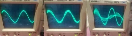
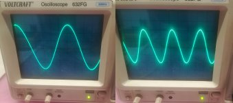
Why is at SOFT filter at firmware 1.19 frequency response rising till 20khz ? Is it deemphasis in script?
In comparisson i put pictures of 1khz, 10khz and 20khz SOFT sine wave and 10khz vs 20khz MINIMUM filter sine wave where we see normal falling response at that frequency.
I already asked but will again.
Why is at SOFT filter at firmware 1.19 frequency response rising till 20khz ? Is it deemphasis in script?
In comparisson i put pictures of 1khz, 10khz and 20khz SOFT sine wave and 10khz vs 20khz MINIMUM filter sine wave where we see normal falling response at that frequency.
Attachments
Last edited:
Can anybody tell me if i can upload old 2k filter F5, F6 into 1.19 firmware or i must downgrade firmware to 1.09? Thank you.
Anyone here tried hooking up two dam1021 to one Toslink?!
Doesn't work for me. I just wired them in parallel but nothing.
Doesn't work for me. I just wired them in parallel but nothing.
please reply to my email for support. any one of the six that i have sent over the last month will do. I dont understand why i have not received any communication regarding the DAc that i sent for repair but please consider getting back to me.
So further modding on,
I've bypassed the 7x05 regulators and set the DIYINHK regulators to 5V accordingly for the entire stack. This also requires the removal of the output muting shunts and R392 resistor. Probably a good idea if you don't trust these shunts in the audio path anyway, I will likely be building a new relay based mute circuit...
Remounted Sparko 3.3V regulators to be much better by using the old serial pin header area for its 3 pins, because they are now being fed 5V they no longer need active heatsinking so the footprint area is much smaller to mount them.
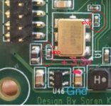
I did this by raising the DOUT pin on the U39 serial interface on the serial header pin that I had to steal for the regulator pin.
The first pin being connected to the ground plane gets you the first pin for the regulator, jumpered the other two regulator pins straight to the pads for the old 3.3LDO.
I tried removing the U32 IC first but that resulted in failure as serial commands no longer reached the board, it seems the RX commands pass back through this chip and some initialization routine requires both the DIN/ROUT pins from the FPGA to be connected or forwarding the data after some set period of time after startup... Soren, is there a good explanation of this? I read the datasheet for the serial converter but it doesn't tell me a whole lot about your code unfortunately. Shorting out the 2 pins for DIN and ROUT allowed the FPGA to receive volume commands after startup, however if these pins are shorted at startup it simply will not lock until the short is removed.
Removed lowpass caps on the r-2r output finally after a few years of being on the fence about it.... just do this, arguably the biggest difference of all, just get rid of them, forever!
I was originally going to run the +/-5V direct via sparko regulators but didn't bother with the added complexity simply because the DIYINHK units appear to output just as clean power or better. There becomes a point where I don't believe there is a whole lot more to milk out of this thing barring going full on battery type setup but thats way outside of my practicality standards.
Now to do more listening. It will be difficult to tell how much each mod did what with regards to the improved SQ, however its likely the lowpass cap removal made the largest difference. Anything from the shunt removal and regulator bypass remains to be heard.
I've bypassed the 7x05 regulators and set the DIYINHK regulators to 5V accordingly for the entire stack. This also requires the removal of the output muting shunts and R392 resistor. Probably a good idea if you don't trust these shunts in the audio path anyway, I will likely be building a new relay based mute circuit...
Remounted Sparko 3.3V regulators to be much better by using the old serial pin header area for its 3 pins, because they are now being fed 5V they no longer need active heatsinking so the footprint area is much smaller to mount them.
I did this by raising the DOUT pin on the U39 serial interface on the serial header pin that I had to steal for the regulator pin.
The first pin being connected to the ground plane gets you the first pin for the regulator, jumpered the other two regulator pins straight to the pads for the old 3.3LDO.
I tried removing the U32 IC first but that resulted in failure as serial commands no longer reached the board, it seems the RX commands pass back through this chip and some initialization routine requires both the DIN/ROUT pins from the FPGA to be connected or forwarding the data after some set period of time after startup... Soren, is there a good explanation of this? I read the datasheet for the serial converter but it doesn't tell me a whole lot about your code unfortunately. Shorting out the 2 pins for DIN and ROUT allowed the FPGA to receive volume commands after startup, however if these pins are shorted at startup it simply will not lock until the short is removed.
Removed lowpass caps on the r-2r output finally after a few years of being on the fence about it.... just do this, arguably the biggest difference of all, just get rid of them, forever!
I was originally going to run the +/-5V direct via sparko regulators but didn't bother with the added complexity simply because the DIYINHK units appear to output just as clean power or better. There becomes a point where I don't believe there is a whole lot more to milk out of this thing barring going full on battery type setup but thats way outside of my practicality standards.
Now to do more listening. It will be difficult to tell how much each mod did what with regards to the improved SQ, however its likely the lowpass cap removal made the largest difference. Anything from the shunt removal and regulator bypass remains to be heard.
Can you tell in a few words what was improved??? In which way... more 3d more relaxed ..? thank you Davorin
Can you tell in a few words what was improved??? In which way... more 3d more relaxed ..? thank you Davorin
I would say more relaxed, there was some points where I found both highs and bass to be a bit emphasized however it feels more relaxed, in a good way. I measured the vref but its noise is lower than my ds1054/1104 can measure which itself isn't a bad thing.
I want to do some much higher listening levels later.
It is definitely more relaxed sounding and the bass seems more precisely defined and blends in better with the rest of it, what I was referring to with highs and lows being emphasized was how it sounded before the most recent set of mods. There is certainly an improvement in just about everything I've been re-listening to. I've basically removed 2 things from the audio path and eliminated the 7x05 regulators. I'm in the process of re-implementing a normally-closed relay based mute circuit.
Soren, which resistor or pin does one need to use to access the mute toggle from the micro? Thanks,
Soren, which resistor or pin does one need to use to access the mute toggle from the micro? Thanks,
Is possible to create and load LP, BP and HP filter in Dam 1021. If yes then this give us possibility to have crossover functionality. 2x dam1021 2-way crossover, 3x dam1021 3-way crossover. And all should be synchronized together .
Yes. Yes. Hard. But id you feed them all from one and the same toslink source they will be synchronized enough I believe. I built a 1 in 4 out toslink splitter with just one receiver, 4 transmitters and a 3,3v supply. Delay will not be available unfortunately.
//
//
TNT
I think synchronization with usb card is better than toslink. I remember I saw somewhere that is possible. Why we need delay?
Anyone was sucessful with creating crossover filter for dam1021?
Maybe Newest XMOS XCORE-200 XU216 can help.
I think synchronization with usb card is better than toslink. I remember I saw somewhere that is possible. Why we need delay?
Anyone was sucessful with creating crossover filter for dam1021?
Maybe Newest XMOS XCORE-200 XU216 can help.
USB would be worse actually due to that there are buffering and protocol handling on the line. This means interrupts and etc processing that could make the duration to pass a data word different between the different USB cables. A Toslink sender, cable and receiver has no such processing.
Maybe we are talking about different synchronisation - I refer to that data words (16bit music) should be send out at the same time between different channels if they where recorded at the same time. This inter channel delay should be zero - or at least constant.
Delay is used to compensate for inter speaker driver time differences.
//
Last edited:
Hello did any on try to Play dsd od dxd Music? I have an soekris with xmos usb and thinking about to convert my flac Music to dsd, but i dont have aby idea it is sens. Becouse dsd and dxd are Good for delta sigma dacs to avoid dac filters.
Just do it real time without converting, for Foobar you have the SACD plugin to play DSD, it converts DSD to PCM or vice versa.
But I don't see a reason to convert flac to DSD, because the Soekris DAC is R-2R.
But I don't see a reason to convert flac to DSD, because the Soekris DAC is R-2R.
I have some new dam1021 firmware for testing, it hopefully should fix the issue some are seeing with small "clicks" on rev 1.19, I can't be certain as only some have issues and my prototypes here don't....
For now it's just the fpga firmware for testing, just down and install as normal, firmware 1.19 must already be loaded, if not install firmware 1.19 first.
http://soekris.dk/download/dam1021/1021fpga_120.skr
Please let me know how it goes asap.
For now it's just the fpga firmware for testing, just down and install as normal, firmware 1.19 must already be loaded, if not install firmware 1.19 first.
http://soekris.dk/download/dam1021/1021fpga_120.skr
Please let me know how it goes asap.
Søren
I've updated my stack and it works fine like before. I did remember random "clicks" in either channel during silence a while back but didn't think anything of it, also I believe it only happened in spdif mode as I haven't noticed it during any close listening (all music listening is done via i2s) but only during silence being fed at 96khz via spdif from my sound card which is all PC based stuff like video, etc.
I've updated my stack and it works fine like before. I did remember random "clicks" in either channel during silence a while back but didn't think anything of it, also I believe it only happened in spdif mode as I haven't noticed it during any close listening (all music listening is done via i2s) but only during silence being fed at 96khz via spdif from my sound card which is all PC based stuff like video, etc.
- Home
- Vendor's Bazaar
- Reference DAC Module - Discrete R-2R Sign Magnitude 24 bit 384 KHz