To my understanding the concepts of clock master and slave apply to the bit clock and frame sync only. For botic it is always assumed that the MCASP is the master for this and not the codec. Indeed the DAI format setting specifies the master / slave configuration between codec and platform as well as other settings and I would assume it needs to be changed for TDM mode.
With regards to the audio master clock (which is divided down to generate the different signals), the botic driver I maintain currently only supports the default configuration of a Hermes - Cronus combination where two different clock frequencies are available on one signal input which can be switched by a GPIO.
Alternative configurations that used to be supported with earlier versions of the driver have not been implemented mainly because I do not use them. Regarding clocks these alternatives are:
- Using only the BBB internal clock for 48k based frequencies (this means no playback / too fast playback for 44.1k based material)
- Using the internal BBB clock together with one external clock for 44.1k
Happy to re-integrate them based on the rewrite of the machine code driver if someone would be willing to put some initial effort into it.
Trouble Integrating Coroner21 Botic Driver in Yocto Linux Distro
Thanks for the insights into the botic clocking design. As I mentioned, I'm a noob when it comes to ASOC driver design and clocking. I tried the following changes:
Unfortunately, when I attempted to configure the card driver to be clk_master=1 I now see pulses on the MCLK pin (P9.25) of the BeagleBone but the rate seems much too low (~4 MHz) for a 16 channel, 32 bit playback example (with blr_ratio=512). I would expect BCLK and FSYNC to be driven as well (since the BeagleBone is providing clocking to an external device) but both clocks were inactive. I was hoping, given my configuration options above, you might be able to offer some suggestions where I might've gone wrong. I also made the ARX0-3 pins both inputs/outputs to accomodate either capture or playback. Perhaps their direction should be mapped to mirror the serconfig settings in the device tree (e.g. set all the pins to 3 rather that 1 or 2)?
Again, any thoughts you might have would be helpful. I'm a bit in the dark at the moment fully understanding how all these clocking settings are related.
Thanks for the insights into the botic clocking design. As I mentioned, I'm a noob when it comes to ASOC driver design and clocking. I tried the following changes:
Code:
Index: git/card/botic-card.c
===================================================================
--- git.orig/card/botic-card.c
+++ git/card/botic-card.c
@@ -23,6 +23,8 @@ static int dai_format = SND_SOC_DAIFMT_C

 static int blr_ratio = 64;

+static int clk_master = 0;
+
 struct botic_priv {
 	unsigned long clk44_freq;
 	unsigned long clk48_freq;
@@ -66,12 +68,12 @@ static int botic_hw_params(struct snd_pc
 	}

 	/* set the codec system clock */
-	ret = snd_soc_dai_set_sysclk(codec_dai, 0, sysclk, SND_SOC_CLOCK_IN);
+	ret = snd_soc_dai_set_sysclk(codec_dai, 0, sysclk, clk_master ? SND_SOC_CLOCK_OUT : SND_SOC_CLOCK_IN);
 	if ((ret < 0) && (ret != -ENOTSUPP))
 		return ret;

 	/* use the external clock */
-	ret = snd_soc_dai_set_sysclk(cpu_dai, 0, sysclk, SND_SOC_CLOCK_IN);
+	ret = snd_soc_dai_set_sysclk(cpu_dai, 0, sysclk, clk_master ? SND_SOC_CLOCK_OUT : SND_SOC_CLOCK_IN);
 	if (ret < 0) {
 		printk(KERN_WARNING "botic-card: unable to set clock to CPU; ret=%d", ret);
 		return ret;
@@ -311,6 +313,9 @@ static struct platform_driver asoc_botic

 module_platform_driver(asoc_botic_card_driver);

+module_param(clk_master, int, 0644);
+MODULE_PARM_DESC(clk_master, "Choose between clock master or slave");
+
 module_param(blr_ratio, int, 0644);
 MODULE_PARM_DESC(blr_ratio, "force BCLK/LRCLK ratio");

Index: git/dts/src/arm/BOTIC-00A0.dts
===================================================================
--- git.orig/dts/src/arm/BOTIC-00A0.dts
+++ git/dts/src/arm/BOTIC-00A0.dts
@@ -78,18 +78,18 @@
 			mcasp0_custom_pins: mcasp0_custom_pins {
 				pinctrl-single,pins = <
 					/* bitclock */
-					AM33XX_IOPAD(0x990, PIN_OUTPUT | MUX_MODE0)	/* mcasp0_aclkx.mcasp0_aclkx */
+					AM33XX_IOPAD(0x990, PIN_OUTPUT | PIN_INPUT | MUX_MODE0)	/* mcasp0_aclkx.mcasp0_aclkx */
 					/* wordclock */
-					AM33XX_IOPAD(0x994, PIN_OUTPUT | MUX_MODE0)	/* mcasp0_fsx.mcasp0_fsx */
+					AM33XX_IOPAD(0x994, PIN_OUTPUT | PIN_INPUT | MUX_MODE0)	/* mcasp0_fsx.mcasp0_fsx */
 					/* data pins */
-					AM33XX_IOPAD(0x998, PIN_OUTPUT | MUX_MODE0)	/* mcasp0_axr0.mcasp0_axr0 */
-					AM33XX_IOPAD(0x9a8, PIN_OUTPUT | MUX_MODE0)    /* mcasp0_axr1 */
+					AM33XX_IOPAD(0x998, PIN_OUTPUT | PIN_INPUT | MUX_MODE0)	/* mcasp0_axr0.mcasp0_axr0 */
+					AM33XX_IOPAD(0x9a8, PIN_OUTPUT | PIN_INPUT | MUX_MODE0)    /* mcasp0_axr1 */
 					/* disable eCAP0_in_PWM0_out to allow usage of mcasp0_axr2 on P9_42 */
 					AM33XX_IOPAD(0x964, PIN_INPUT | MUX_MODE7)              /* ecap0_in_pwm0_out.gpio0_7 */
-					AM33XX_IOPAD(0x9a0, PIN_OUTPUT | MUX_MODE2)	/* mcasp0_aclkr.mcasp0_axr2 */
-					AM33XX_IOPAD(0x9a4, PIN_OUTPUT | MUX_MODE2)    /* mcasp0_fsr.mcasp0_axr3 */
+					AM33XX_IOPAD(0x9a0, PIN_OUTPUT | PIN_INPUT | MUX_MODE2)	/* mcasp0_aclkr.mcasp0_axr2 */
+					AM33XX_IOPAD(0x9a4, PIN_OUTPUT | PIN_INPUT | MUX_MODE2)    /* mcasp0_fsr.mcasp0_axr3 */
 					/* master clock */
-					AM33XX_IOPAD(0x9ac, PIN_INPUT | MUX_MODE0)	/* MCASP0_AHCLKX -> MCASP0_AHCLKX (I2S_MCLK_OUT)- in */
+					AM33XX_IOPAD(0x9ac, PIN_OUTPUT | PIN_INPUT | MUX_MODE0)	/* MCASP0_AHCLKX -> MCASP0_AHCLKX (I2S_MCLK_OUT)- in */

 				>;
 			};
Unfortunately, when I attempted to configure the card driver to be clk_master=1 I now see pulses on the MCLK pin (P9.25) of the BeagleBone but the rate seems much too low (~4 MHz) for a 16 channel, 32 bit playback example (with blr_ratio=512). I would expect BCLK and FSYNC to be driven as well (since the BeagleBone is providing clocking to an external device) but both clocks were inactive. I was hoping, given my configuration options above, you might be able to offer some suggestions where I might've gone wrong. I also made the ARX0-3 pins both inputs/outputs to accomodate either capture or playback. Perhaps their direction should be mapped to mirror the serconfig settings in the device tree (e.g. set all the pins to 3 rather that 1 or 2)?
Again, any thoughts you might have would be helpful. I'm a bit in the dark at the moment fully understanding how all these clocking settings are related.
You can get acquainted with the beta versions: Botic7 — Yandex.Disk
Description and changelog in Russian. But for the release, I will prepare documentation in English.
Temporarily support for this firmware on the Russian forum:
Сетевой плеер на Beaglebone Black — чистое удовольствие - Цифровые источники - DA Stereo
In the near future I will make partial support for WiFi USB.
Tks so much.
If only use the BBB as streamers. Your images are very fast on/off <3s, and easily for the change other protocol in 1s direct on web browser, easy for new user linux system. I very like it.
Lets take this offline since your configuration and hardware do not really seem to be the standard people are talking about here. I will respond via PM.Thanks for the insights into the botic clocking design. As I mentioned, I'm a noob when it comes to ASOC driver design and clocking. I tried the following changes:
Unfortunately, when I attempted to configure the card driver to be clk_master=1 I now see pulses on the MCLK pin (P9.25) of the BeagleBone but the rate seems much too low (~4 MHz) for a 16 channel, 32 bit playback example (with blr_ratio=512). I would expect BCLK and FSYNC to be driven as well (since the BeagleBone is providing clocking to an external device) but both clocks were inactive. I was hoping, given my configuration options above, you might be able to offer some suggestions where I might've gone wrong. I also made the ARX0-3 pins both inputs/outputs to accomodate either capture or playback. Perhaps their direction should be mapped to mirror the serconfig settings in the device tree (e.g. set all the pins to 3 rather that 1 or 2)?Code:Index: git/card/botic-card.c =================================================================== --- git.orig/card/botic-card.c +++ git/card/botic-card.c @@ -23,6 +23,8 @@ static int dai_format = SND_SOC_DAIFMT_C static int blr_ratio = 64; +static int clk_master = 0; + struct botic_priv { unsigned long clk44_freq; unsigned long clk48_freq; @@ -66,12 +68,12 @@ static int botic_hw_params(struct snd_pc } /* set the codec system clock */ - ret = snd_soc_dai_set_sysclk(codec_dai, 0, sysclk, SND_SOC_CLOCK_IN); + ret = snd_soc_dai_set_sysclk(codec_dai, 0, sysclk, clk_master ? SND_SOC_CLOCK_OUT : SND_SOC_CLOCK_IN); if ((ret < 0) && (ret != -ENOTSUPP)) return ret; /* use the external clock */ - ret = snd_soc_dai_set_sysclk(cpu_dai, 0, sysclk, SND_SOC_CLOCK_IN); + ret = snd_soc_dai_set_sysclk(cpu_dai, 0, sysclk, clk_master ? SND_SOC_CLOCK_OUT : SND_SOC_CLOCK_IN); if (ret < 0) { printk(KERN_WARNING "botic-card: unable to set clock to CPU; ret=%d", ret); return ret; @@ -311,6 +313,9 @@ static struct platform_driver asoc_botic module_platform_driver(asoc_botic_card_driver); +module_param(clk_master, int, 0644); +MODULE_PARM_DESC(clk_master, "Choose between clock master or slave"); + module_param(blr_ratio, int, 0644); MODULE_PARM_DESC(blr_ratio, "force BCLK/LRCLK ratio"); Index: git/dts/src/arm/BOTIC-00A0.dts =================================================================== --- git.orig/dts/src/arm/BOTIC-00A0.dts +++ git/dts/src/arm/BOTIC-00A0.dts @@ -78,18 +78,18 @@ mcasp0_custom_pins: mcasp0_custom_pins { pinctrl-single,pins = < /* bitclock */ - AM33XX_IOPAD(0x990, PIN_OUTPUT | MUX_MODE0) /* mcasp0_aclkx.mcasp0_aclkx */ + AM33XX_IOPAD(0x990, PIN_OUTPUT | PIN_INPUT | MUX_MODE0) /* mcasp0_aclkx.mcasp0_aclkx */ /* wordclock */ - AM33XX_IOPAD(0x994, PIN_OUTPUT | MUX_MODE0) /* mcasp0_fsx.mcasp0_fsx */ + AM33XX_IOPAD(0x994, PIN_OUTPUT | PIN_INPUT | MUX_MODE0) /* mcasp0_fsx.mcasp0_fsx */ /* data pins */ - AM33XX_IOPAD(0x998, PIN_OUTPUT | MUX_MODE0) /* mcasp0_axr0.mcasp0_axr0 */ - AM33XX_IOPAD(0x9a8, PIN_OUTPUT | MUX_MODE0) /* mcasp0_axr1 */ + AM33XX_IOPAD(0x998, PIN_OUTPUT | PIN_INPUT | MUX_MODE0) /* mcasp0_axr0.mcasp0_axr0 */ + AM33XX_IOPAD(0x9a8, PIN_OUTPUT | PIN_INPUT | MUX_MODE0) /* mcasp0_axr1 */ /* disable eCAP0_in_PWM0_out to allow usage of mcasp0_axr2 on P9_42 */ AM33XX_IOPAD(0x964, PIN_INPUT | MUX_MODE7) /* ecap0_in_pwm0_out.gpio0_7 */ - AM33XX_IOPAD(0x9a0, PIN_OUTPUT | MUX_MODE2) /* mcasp0_aclkr.mcasp0_axr2 */ - AM33XX_IOPAD(0x9a4, PIN_OUTPUT | MUX_MODE2) /* mcasp0_fsr.mcasp0_axr3 */ + AM33XX_IOPAD(0x9a0, PIN_OUTPUT | PIN_INPUT | MUX_MODE2) /* mcasp0_aclkr.mcasp0_axr2 */ + AM33XX_IOPAD(0x9a4, PIN_OUTPUT | PIN_INPUT | MUX_MODE2) /* mcasp0_fsr.mcasp0_axr3 */ /* master clock */ - AM33XX_IOPAD(0x9ac, PIN_INPUT | MUX_MODE0) /* MCASP0_AHCLKX -> MCASP0_AHCLKX (I2S_MCLK_OUT)- in */ + AM33XX_IOPAD(0x9ac, PIN_OUTPUT | PIN_INPUT | MUX_MODE0) /* MCASP0_AHCLKX -> MCASP0_AHCLKX (I2S_MCLK_OUT)- in */ >; };
Again, any thoughts you might have would be helpful. I'm a bit in the dark at the moment fully understanding how all these clocking settings are related.
Dear more experiences colleagues. I would like to ask you about help. For one project I need 4 channels DSD only NAA for HQPlayer. I bought BBB rev. C. It looks promise, BBB has external oscillators input on P9/25 and clock selection output on P9/24. Also has 4 usable serializers:
P9/27 mcasp0_axr3 (data3) = DSD4,
P9/30 mcasp0_axr0 (data0) = DSD1,
P9/41 mcasp0_axr1 (data1) = DSD2,
P9/42 or 28 mcasp0_axr2 (data2) = DSD3,
P9/31 DSD clock.
I do not need DSD ON, LRCLK, BCLK…, but MUTE signal can be useful, but I don’t know, where can be remapped from commonly used P9/27.
Can you recommended me which present system and driver can fit these requirements? And can you help me with some important steps, how can go through. I am hardware guy and not familiar with Linux, Botic …
Thanks a lot
exactly, that`s a good question.
Can the Mute pin applied when those 4 pins are used for Data?
From Miero`s web site:
--------
Mute pin
--------
Notice: This parameter is available in botic7
Emulation of mute pin on some of 1-4 data pins:
- kernel option snd_soc_davinci_mcasp.mute_pin
- file /sys/module/snd_soc_davinci_mcasp/parameters/mute_pin
which can be updated while system is running, but change
will be applied on the next start of playback
Supported values for mute_pin:
-1 ... mute pin functionality is disabled
or these additive numbers:
+ 1 ... signal mute on pin 0
+ 2 ... signal mute on pin 1
+ 4 ... signal mute on pin 2
+ 8 ... signal mute on pin 3
+ 16777216 ... invert the mute signal
It seems the Mute Pin is just another Data signal, so with a Mute pin enabled the maximum PCM channels are 6 and the maximum DSD channels are 3?
Any option to use different pins, or is this the result of having to give up 1 serializer for a Mute pin?
Guys, anybody have an idea to get 4 DSD channels as well as 1 mute pin?
Dear more experiences colleagues. I would like to ask you about help. For one project I need 4 channels DSD only NAA for HQPlayer. I bought BBB rev. C. It looks promise, BBB has external oscillators input on P9/25 and clock selection output on P9/24. Also has 4 usable serializers:
P9/27 mcasp0_axr3 (data3) = DSD4,
P9/30 mcasp0_axr0 (data0) = DSD1,
P9/41 mcasp0_axr1 (data1) = DSD2,
P9/42 or 28 mcasp0_axr2 (data2) = DSD3,
P9/31 DSD clock.
I do not need DSD ON, LRCLK, BCLK…, but MUTE signal can be useful, but I don’t know, where can be remapped from commonly used P9/27.
Can you recommended me which present system and driver can fit these requirements? And can you help me with some important steps, how can go through. I am hardware guy and not familiar with Linux, Botic …
Thanks a lot
Jan, if you look here:
Botic7 — Yandex.Disk
at the Readme english file at the bottom it says:
"When working via I2S, it is possible to use two types of mute signal
1. Signal generated by the driver - 27 pin P9
2. The signal generated by the system based on data from the players and the Alsa subsystem - 28 pin P9.
Setting in the script /opt/mutedsc2.sh
The firmware has standard user settings via the web interface Nymeria
Shell access via SSH - root / root"
You could try that and see if it works.
Marco
I am afraid that P9/27 and P9/28 are booth serializers outputs and BBB has only 4 serializers. MUTE signal looks similar as DSD ON signal. For DSD only DAC don’t need DSD ON signal, so it can be useful replace it by MUTE. Or the best I think will be on P9/26 have something like NOR(DSD On) OR MUTE signal. Or use any another pin then P9/24, 25, 27, 31, 30, 41, 42 (28). Any idea?
DSC2 mute pin support
@coroner21, thank you for your contributions here and on GitHub. You were spot on in these recommendations to get the DSC2 mute pin working without hacking the McASP driver (would be awesome if the sample rate changes could be upstreamed to the linux mainline to avoid patching that at all...).
I was able to get your module at GitHub - coroner21/botic-modules: DKMS modules for the botic driver working with a modern kernel (latest-ish GitHub - beagleboard/linux: The official BeagleBoard and BeagleBone kernel repository RT release) for @ppy's DSC2. All that was need were changes to the DTS (move serializer -> GPIO, and changing clock order in the mux for DSC2) and utilizing this GPIO in the codec for mute_stream events.
I currently have my changes in a buildroot-based OS I've created for the DSC2. Happy to try to get these changes generalized upstream in your module and then pull from your repo during my buildroot packaging. I think if switched to `gpiod_get_optional`in the codec it could be simply configurable via the DTS.
Thanks again for your work to modernize this module!
Greg
I see that you use AXR3 / GPIO3_19 as mute pin. Rather than hacking the GPIO usage into the McASP module, it would be much more easy in your case to simply setup the McASP to use two serializers only (AXR0 / AXR1 as required for two DSD channels).
My suggestion would be then to integrate the mute rather in the generic BOTIC codec as an optional GPIO that is claimed in case it is configured in the device tree as part of the codec node (e.g. mute-gpios = <&gpio3 19 0>) and implement the digital_mute function as part of the snd_soc_dai_ops for the codec. If you are willing to test this, I can quickly add the required code to the Arch Linux ARM kernel and provide instructions. Unfortunately I have no way of testing it myself since the ESS DACs seem to do just fine even without any mute being applied.
Also in your case (since you know that you want to only support DSD sample formats) it might make sense to change the botic-codec definitions so that they only include DSD. That way you would not even need the DSD switch since ALSA would already error out.
@coroner21, thank you for your contributions here and on GitHub. You were spot on in these recommendations to get the DSC2 mute pin working without hacking the McASP driver (would be awesome if the sample rate changes could be upstreamed to the linux mainline to avoid patching that at all...).
I was able to get your module at GitHub - coroner21/botic-modules: DKMS modules for the botic driver working with a modern kernel (latest-ish GitHub - beagleboard/linux: The official BeagleBoard and BeagleBone kernel repository RT release) for @ppy's DSC2. All that was need were changes to the DTS (move serializer -> GPIO, and changing clock order in the mux for DSC2) and utilizing this GPIO in the codec for mute_stream events.
I currently have my changes in a buildroot-based OS I've created for the DSC2. Happy to try to get these changes generalized upstream in your module and then pull from your repo during my buildroot packaging. I think if switched to `gpiod_get_optional`in the codec it could be simply configurable via the DTS.
Thanks again for your work to modernize this module!
Greg
Hi Greg,
Very happy to see someone making more use of the work I put into this! Changes look good, I understand you are using a different clock order for the DSC2 and therefore have to change the order in the DTS? Note that the actual serializer config for McASP does not matter much since it has no effect on the pin config, so you could leave that unchanged.
Would be happy to pull in your changes into my repo, please feel free to send a pull request. I would prefer then to use a separate DTS-file for the DSC2 and make the GPIO in the botic codec indeed optional.
Note that I recently updated the master branch to work on 5.10 kernels (since archlinux ARM was just updated) and will create a separate 5.10 branch for this LTS release based on this.
Best,
Christian
Last edited:
I need BBB+Botic fixed 32-bit output endpoint side. Pls help ����
There are many different 16/20/24/32-bit music sources from Musaic Sever. example my DAC only supports 16bit. So I need BBB + Botic synchronous fixed output endpoint which is 16-bit.
Then just go ahead and see how you can achieve what you want and if you face a particular problem or are stuck anywhere ask a concrete question... 🙂
There are many different 16/20/24/32-bit music sources from Musaic Sever. example my DAC only supports 16bit. So I need BBB + Botic synchronous fixed output endpoint which is 16-bit.
You can probably solve this problem by adding a format line restricting ALSA to S16LE. You can also easily make the system stop working by mid-configuring ALSA. You should read and study before editing ALSA.conf. Good luck!
My first experience with building firmware for SBC. Do not judge strictly.
"Pure" firmware for BeagleBone
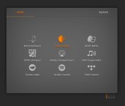
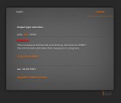
Audio endpoint for NAA, RAAT, UPNP, AirPlay, LMS, Spotify Connect, TidalConnect and multicast streaming. This firmware supports three types of output - USB, I2S and SPDIF.
GitHub - ppy2/pure
Kernel 4.9.146 and Botic7
GitHub - ppy2/kernel_botic7
"Pure" firmware for BeagleBone
Audio endpoint for NAA, RAAT, UPNP, AirPlay, LMS, Spotify Connect, TidalConnect and multicast streaming. This firmware supports three types of output - USB, I2S and SPDIF.
GitHub - ppy2/pure
Kernel 4.9.146 and Botic7
GitHub - ppy2/kernel_botic7
Attachments
Compiled image
Pure_18_03_2021.gz — Yandex.Disk
Hi PPY,
I am having problem installing Pure firmware on BBB.... 🙁 !!!
I am using Botic7 firmware installed in BBB with DSC2 very well.
But with Pure firmware, webbrowse on my PC can't connect to BBB, HQplayer Desktop can't connect.
I have followed the steps to copy Pure firmware to SD card according to your instructions and just like with Botic7 firmware.
Is Pure firmware only used with DSDit? Or have to take other steps?
Tksss!
Last edited:
- Home
- More Vendors...
- Twisted Pear
- Support for Botic Linux driver