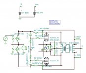
This is anode feedback. It has 0.06% at 45w and has slightly higher DF as the ratio is 50% instead of 40%. The sensitivity is less than 0.5Vp which gives the possibility to feedback anode to cathode. The cascode is biased only 1.5ma that enables the use of TO92 transistor.. The 6H30 works at 60v 20ma, after which pull up resistor is necessary on the anode to let only 1.5 of it to the cascode. If you bring the sensitivity to 2.5v by extra feedback, than the distortion goes 5times lower and the DF 5 times higher.
Attachments
Thanks, great info! 0,5Vp could give space to the use of the trafo with 33% UL and 10% CFB that I've linked few post above. Can I ask you how you measure the DF?
This evening I will sketch the schematic to see if I've understood correctly your suggestions.
This evening I will sketch the schematic to see if I've understood correctly your suggestions.
You apply a current source on the output and you measure the voltage, you get the output impedance to divide the load. You verify that at low power and high you have the same value or else to adjust the bias.
Thanks kokoriantz!
I've done some research and I've found that the power amp with the 6H30 is Allen Wright's PP-2C with KT88, that is no more on his site but it's available here: http://svle.free.fr/p845/PP-2C_map.pdf
While here there's the datasheet of the 6H30:
https://headwizememorial.files.wordpress.com/2018/03/6h30a.gif
https://headwizememorial.files.wordpress.com/2018/03/6h30b.gif
I'm using the configuration of fig. 2.46 page 136 of Morgan Jones's Valve Amplifiers ( http://milas.spb.ru/~kmg/files/literature/Morgan_Jones_Valve_Amplifiers_Third_Edition.pdf ) and I have found the right current on the bottom triode (22 mA, in between 40 and 5 mA, limits of linearity for the specific tube) with a 10 kOhm resistor from triode's anode to B+. But I have troubles in finding the right configuration for the upper BJT.
Can I please ask a sketch?
Thanks in advance.
Last edited:
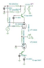
100 ohms on cathodes falls the u from 5ma/V to 2.5ma/V to allow some feedback on the cathodes. The mje13001 I tried the 13007, the capacitance is too high limiting 20khz, the KSC1845 needs protection on start up. Of course you can replace with tubes.
Attachments
Last edited:
The MJE13001 should be ok, I don't find any spice model although it is used in small phone chargers.

If I do it, I'm no more able to balance the system, nor to reach full swing.get ride of R12/13.
Here it is the models I'm using:
Code:
* Generic triode model: 6H30
* Copyright 2003--2008 by Ayumi Nakabayashi, All rights reserved.
* Version 3.10, Generated on Tue Aug 10 23:01:40 2010
*            Plate
*            | Grid
*            | | Cathode
*            | | |
.SUBCKT 6H30 A G K
.PARAM X1=1 X2=0.0016665882 X3=-0.038461562
.PARAM X4=0.97499998 X5=15.000715 X6=1.5384616
.PARAM X7=0.0038313265 X8=15.385349 X9=0.003327778
.PARAM Y1=0.0019156633 Y2=0.0022952053
BK IK 0 V=U(V(G,K)+X1)*X7*URAMP(V(G,K)+X1+URAMP(V(A,K))/X8)**1.5+(1-U(V(G,K)+X1))*X9*(X2*URAMP(V(A,K)))**X3*(X4*URAMP(V (G,K)+X1+URAMP(V(A,K))/X5))**X6
BA A K I=URAMP((Y2*URAMP(V(A,K))**1.5)-URAMP((Y2*URAMP(V(A,K))**1.5)-V(IK)+Y1*URAMP(V(G,K))**1.5*(URAMP(V(G,K))/(URAMP(V(A,K))+URAMP(V(G,K)))*1.2+.4)))+1E-10*V(A,K)
BG G K I=Y1*URAMP(V(G,K))**1.5*(URAMP(V(G,K))/(URAMP(V(A,K))+URAMP(V(G,K)))*1.2+.4)
* CAPS
CGA G A 5p
CGK G K 6.3p
CAK A K 2.4p
.ENDS
Code:
* Generic pentode model: EL34
* Copyright 2003--2008 by Ayumi Nakabayashi, All rights reserved.
* Version 3.10, Generated on Sat Mar  8 22:42:48 2008
*            Plate
*            | Screen Grid
*            | | Control Grid
*            | | | Cathode
*            | | | |
.SUBCKT EL34 A G2 G1 K
BGG   GG   0 V=V(G1,K)+0.29360503
BM1   M1   0 V=(0.040003405*(URAMP(V(G2,K))+1e-10))**-0.73308055
BM2   M2   0 V=(0.67171782*(URAMP(V(GG)+URAMP(V(G2,K))/8.2063559)))**2.2330806
BP    P    0 V=0.0033402929*(URAMP(V(GG)+URAMP(V(G2,K))/12.216969))**1.5
BIK   IK   0 V=U(V(GG))*V(P)+(1-U(V(GG)))*0.0019762451*V(M1)*V(M2)
BIG   IG   0 V=0.0016701465*URAMP(V(G1,K))**1.5*(URAMP(V(G1,K))/(URAMP(V(A,K))+URAMP(V(G1,K)))*1.2+0.4)
BIK2  IK2  0 V=V(IK,IG)*(1-0.4*(EXP(-URAMP(V(A,K))/URAMP(V(G2,K))*15)-EXP(-15)))
BIG2T IG2T 0 V=V(IK2)*(0.87617414*(1-URAMP(V(A,K))/(URAMP(V(A,K))+10))**1.5+0.12382586)
BIK3  IK3  0 V=V(IK2)*(URAMP(V(A,K))+1250)/(URAMP(V(G2,K))+1250)
BIK4  IK4  0 V=V(IK3)-URAMP(V(IK3)-(0.0020885491*(URAMP(V(A,K))+URAMP(URAMP(V(G2,K))-URAMP(V(A,K))))**1.5))
BIP   IP   0 V=URAMP(V(IK4,IG2T)-URAMP(V(IK4,IG2T)-(0.0020885491*URAMP(V(A,K))**1.5)))
BIAK  A    K I=V(IP)+1e-10*V(A,K)
BIG2  G2   K I=URAMP(V(IK4,IP))
BIGK  G1   K I=V(IG)
* CAPS
CGA   G1  A  1.1p
CGK   G1  K  9.1p
C12   G1  G2 6.1p
CAK   A   K  8.4p
.ENDSIt must work without. Get ride of and adjust the pull up resistors 20k to get about 130v on the collectors. 130-60=70v the transistor can swing-70v, more than -38v bias.If I do it, I'm no more able to balance the system, nor to reach full swing.
get ride of R12/13.
Find high voltage mosfet with little capacitors.
R12/R13 are the cascode load resistors, he can't get rid of them. Although they are still too high a value I think.
I agree, it is need, The bias resistor 220k can go up to 0.5M according the datasheet, to higher back the feedback ratio. The cathode resistors 50 ohms can receive both differential feedback from the output, leaving the secondary floating.
Thank you both.
Instead of keep it floating, being a 0-4-8-16 Ohm secondary I'd ground the 4Ohm tap to apply differential feedback to 6H30's cathodes.
I will try the CFB option too.
Can be PowerDrive a solution to easily keep that feedback ratio while being able to properly drive the grids of the EL34, or it's easier to find a mosfet able to get more current, waste more power, and lower both 220k resistors to 47k? Would it be also better?
I kept your circuit but I added overall feedback. You don't see much difference here but in real world it decreases the transformer distortion extends the frequency response at low powers and increases DF. 88w with 0.4% measured by the load current.
Add mosfet only if you want class AB₂, or else it is gadget.
Instead of using .INC use .LIB and add a txt file with all spice models just added in queue. I added mje13001.
Add mosfet only if you want class AB₂, or else it is gadget.
Instead of using .INC use .LIB and add a txt file with all spice models just added in queue. I added mje13001.
Attachments
Last edited:
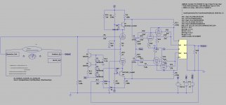
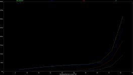
I agree that a combination of local and global feedback would work the best. Attached is another possibility. Cascode load reduced to 100k, reduced the 6H30 current, adjusted local feedback and global feed back to give approximately equal amounts of both, with 1V rms for full output. Distortion vs power is shown, looks quite good.
I included the protection diodes for the cascode transistors. These prevent excessive Vbe on startup when the tube isn't conducting yet.
I included the protection diodes for the cascode transistors. These prevent excessive Vbe on startup when the tube isn't conducting yet.
Attachments
If you want to apply voltage feedback, bring the cathode resistors to zero to get maximum gain, and deal with stability. With current feedback of 10db, the stability is much easier as the whole input stage becomes transparent.
Last edited:
Thanks to you both,
those two 50 Ohm resistors on the cathodes of the 6H30/6N30 are a single 100 Ohm potentiometer ( like this one: Tube-Town Store - Rheostat Alpha 100 Ohm / 5 Watt ) to balance the PI.
Kokoriantz, how would you implement the current feedback?
those two 50 Ohm resistors on the cathodes of the 6H30/6N30 are a single 100 Ohm potentiometer ( like this one: Tube-Town Store - Rheostat Alpha 100 Ohm / 5 Watt ) to balance the PI.
Kokoriantz, how would you implement the current feedback?
- Home
- Amplifiers
- Tubes / Valves
- Question re Allen Wright PP-1cs