What it is:
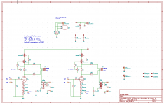
A single tube hybrid parafeed line stage using a single 6N6P - should work with the 6H30 as well utilizing Lundahl LL1930. This is not intended to be an ultimate design, but a cost effective design with transformer.
Each channel comprises half the 6N6P, a cascode CCS using DN2540 or similar, the transformer and a DC blocking capacitor. LED bias is used. Resistors are 1206 or 2512 SMDs.
There are two options for connecting the transformer; jumper configurable; one is directly to the plate of the 6N6P, the other is to the source of the lower device in the cascode. The LL1930 expects to see a source impedance of 4.5K or so and provision is present for padding resistors to satisfy that requirement. (There is obviously a small loss in gain.)
Gain is approximately 8 - 9dB
Frequency response 20 - 30khz @ 1dB or better
Output impedance should be < 150 ohms typical.
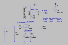
Distortion is predicted at 0.3% at 2Vrms out and is predominantly 2nd with 3rd about 20dB further down, not betting that is an accurate prediction. [Edit: This was way off, THD is typically 0.006% or less]
Both balanced and unbalanced output is possible, input is unbalanced only and is intended for connection to a 50 or 100K pot or stepped attenuator. I will be using a 50K stepped attenuator of dubious origins. (read inexpensive)
I've completed the design, but have not built or tested it yet, that's next.
Power supply will likely be unregulated and lightly filtered since the PSRR will be reasonably high. I will design that next.
Power transformer is an open guess at this point, raw DC voltages in the range of 230 - 300VDC are required. Filament power may/may not be AC, proximity to sensitive circuitry may drive the use of a cheap monolithic regulator for the filament supply.
I ordered the PCB from JLCPCB tonight and will order the rest of the parts (DigiKey) in the next few days.
The name is a bit of an inside joke, I recently designed a line stage using some left over discrete jfet input op-amps I designed which uses a heavily filtered dc to dc converter for power and is very compact. I called it the Cheesy Line Stage because it was supposed to be cheap. (It really wasn't) Trying to keep entertained in these times so I am doing cheesy line stage designs, the last was solid state, this one will be hybrid. After this I will move on and do something else.
A single tube hybrid parafeed line stage using a single 6N6P - should work with the 6H30 as well utilizing Lundahl LL1930. This is not intended to be an ultimate design, but a cost effective design with transformer.
Each channel comprises half the 6N6P, a cascode CCS using DN2540 or similar, the transformer and a DC blocking capacitor. LED bias is used. Resistors are 1206 or 2512 SMDs.
There are two options for connecting the transformer; jumper configurable; one is directly to the plate of the 6N6P, the other is to the source of the lower device in the cascode. The LL1930 expects to see a source impedance of 4.5K or so and provision is present for padding resistors to satisfy that requirement. (There is obviously a small loss in gain.)
Gain is approximately 8 - 9dB
Frequency response 20 - 30khz @ 1dB or better
Output impedance should be < 150 ohms typical.
Distortion is predicted at 0.3% at 2Vrms out and is predominantly 2nd with 3rd about 20dB further down, not betting that is an accurate prediction. [Edit: This was way off, THD is typically 0.006% or less]
Both balanced and unbalanced output is possible, input is unbalanced only and is intended for connection to a 50 or 100K pot or stepped attenuator. I will be using a 50K stepped attenuator of dubious origins. (read inexpensive)
I've completed the design, but have not built or tested it yet, that's next.
Power supply will likely be unregulated and lightly filtered since the PSRR will be reasonably high. I will design that next.
Power transformer is an open guess at this point, raw DC voltages in the range of 230 - 300VDC are required. Filament power may/may not be AC, proximity to sensitive circuitry may drive the use of a cheap monolithic regulator for the filament supply.
I ordered the PCB from JLCPCB tonight and will order the rest of the parts (DigiKey) in the next few days.
The name is a bit of an inside joke, I recently designed a line stage using some left over discrete jfet input op-amps I designed which uses a heavily filtered dc to dc converter for power and is very compact. I called it the Cheesy Line Stage because it was supposed to be cheap. (It really wasn't) Trying to keep entertained in these times so I am doing cheesy line stage designs, the last was solid state, this one will be hybrid. After this I will move on and do something else.
Attachments
The LL1930 expects to see a source impedance of 4.5K or so and provision is present for padding resistors to satisfy that requirement.
Have you confirmed the presence of a higher resonance peak with lower driving impedances? Lundahl does not offer data on parallel primary connection and this may also be worth examining.
How do you predict such a high thd? In sims? Have not tested the 6N6P but a 6H30P wot has a much lower distortion above 100Hz.
I have done measurements on the LL1930 in the past and saw significant peaking so the build out resistors are there to provide an option to optimize the response.
Yes, the simulation is suspect - I am not quite sure what to expect but it's not unlikely that the THD will be much, much lower. I need to measure, will do simple THD to start and later will do an FFT.
I've been doing mostly solid state for the past couple of years so this marks a return to tubes for me.
I thought it would be interesting to see how far I can push things on a comparatively (and deliberately) modest budget.
This is mainly for entertainment, to keep me occupied in my spare time since our social lives are on hold for the moment, and as a comparison to the previous solid state cheesy which has has pretty good measured performance, and sounds nice.
I'm going to start putting together a shopping cart on DigiKey this evening. I will share a link to it once that seems appropriate. (i.e. Once I am sure I have not done something egregiously wrong with the board design.)
The boards are already in fab and will probably be here by next week end. I'll keep posting progress/lack of same updates.
I need to think about long term PSU solution, I think some sort of soft start/delayed B+ is a good idea given it's a parafeed and there is a coupling cap that needs to charge gently to avoid a huge pulse on the output when the power is turned on. I'm almost, and bizarrely thinking this might actually be a job for 6V4 or similar and would make choice of PT easier. There are other silicon options I can pursue which are ultimately more complex but maybe less expensive.
I suggest, that try cascode CCS loaded 6N6P too (without parafeed).
The "low Z" output of CCS provides enough low impedance to drive anything.
If it not enough low, bypassing LEDs with 100...470uF helps in the lower regions.
Indeed that is an option, but I don't need 26dB of gain and will need the option for balanced out. Most people don't need that sort of gain, and if you look at some of my other designs you will see I do something similar in some of my phono amplifier designs (using 6S3P-EV)
If you need balanced, must to connect transformer 6, 9 pin to balanced output "gnd" ... and IMHO it not to tie to preamp GND.
BTW if you use such "high" gain tube, you must adjust volume at input (potmeter), and then relatively low input signal generates lower distortion, than near full swing.
BTW if you use such "high" gain tube, you must adjust volume at input (potmeter), and then relatively low input signal generates lower distortion, than near full swing.
Long experience with pro-sound electronics design taught me long ago that a ground connection on a balanced output is a no-no - for galvanic isolation and some other reasons I don't follow Lundahl's advice. I may at some point raise this question with them. I've tested the connection I used with this transformer and it works exactly as I would expect.
I've designed a fair amount of transformer coupled tube audio that I haven't shared here and my entire system runs balanced mostly with transformer coupling which have no reference to GND on the external connection side of things. A lightning strike outside of the house damaged several devices with balanced solid state inputs and outputs that are ground referenced which provided a path for ground lift through the safety earths to damage the solid state front ends, but none of the transformer coupled gear was affected. (I had to replace op-amps and some balanced input amplifier ICs to repair, design changes made prevented damage when the same thing happened again a year ago.)
Yes, there is a pot or stepped attenuator that goes in front of this. And it would be easy to omit the transformer and add an external coupling capacitor and resistor for a direct output. And yes, distortion would likely be lower - talking of which the spice simulation may be highly pessimistic, based on prior experience I would expect much lower distortion than the analysis shows.
In my case I don't want or need the additional gain, others might need it. Omitting the transformer and adding an external coupling capacitor and resistor is easily accomplished if someone wanted to go this route.
A bigger problem is I attempted to order some DN2540 last night and found they are on back order until May of next year. The same with suitable depletion mode mosfets from IXYs as well. I believe I have enough lurking around here to complete my own prototype, but finding suitable substitutes may be an issue.
Mouser has in stock IXTP08N100.
https://www2.mouser.com/ProductDeta...aOdzbeEZaa1cY3LzWjIAeFEV6Ml9XsqXdkGAv%2BkLg==
Use it as "upper" FET.
https://www2.mouser.com/ProductDeta...aOdzbeEZaa1cY3LzWjIAeFEV6Ml9XsqXdkGAv%2BkLg==
Use it as "upper" FET.
As bottom device I use DN2540N3 TO92 FET.
BTW TME has 08N50.
IXTP08N50D2 IXYS - Transistor: N-MOSFET | unipolar; 500V; 0.8A; 60W; TO220-3; 11ns | TME - Electronic components
BTW TME has 08N50.
IXTP08N50D2 IXYS - Transistor: N-MOSFET | unipolar; 500V; 0.8A; 60W; TO220-3; 11ns | TME - Electronic components
Last edited:
I lost several DN2540 as "upper" device near 350..400V (probably due PSU spikes), so I exclusively use 1kV IXYS FETs there.
As the "bottom" device TO92 DN2540 is appropriate, but working it's lower limit (to low Vgs, below 2V), so there the Crss is growing rapidly, thus upper HF behaviour of CCS would be limited.
As the "bottom" device TO92 DN2540 is appropriate, but working it's lower limit (to low Vgs, below 2V), so there the Crss is growing rapidly, thus upper HF behaviour of CCS would be limited.
I've used DN2540/DN2540 but not at voltages over 300V, and IXTP08N50D2/IXTP08N100D2 to 450V without problems in either case.
It's been a long time since I thought about the crss issue, but it is a problem with all cascodes using any of these depletion mode mosfets, I have a vague recollection of attempting to use lithium primary cells to bias the upper device a few volts higher giving around 5Vds on the lower device - as I recall I had a leakage issue discharging the cells. So long ago that I no longer remember the exact details.
I'm actually considering something a bit odder.
I run them typically in the 10 - 20mA range depending on application with tubes like the D3A, 6S3P/6S4P, 417A/5842 and now 6N6P. This application is aimed at around 15mA, I can go a little higher before plate dissipation becomes a concern in the 6N6P.
In some samples the transconductance can be pretty low at these currents, I would expect something in the range of 0.05S typically, as mosfets go these are not particularly high transconductance devices to start with, even so still way higher than most tubes.
In some samples the transconductance can be pretty low at these currents, I would expect something in the range of 0.05S typically, as mosfets go these are not particularly high transconductance devices to start with, even so still way higher than most tubes.
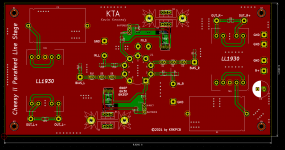
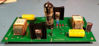
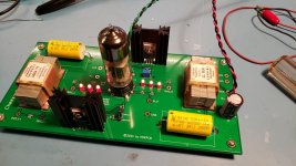
So I built my prototype board tonight, the rest of the boards are spoken for. Testing to follow in the next few days.
Made a couple of minor changes when I built it:
Q2, Q4 > Changed from DN2540 to IXCP10M45S
R9, R21 > Changed from 10.0K to 15.0K
Given the general lack of interest here I have decided to distribute Gerbers to any interested members by email only. I am not interested in the sole beneficiaries being sellers on eBay. I don't expect a stampede.
The power supply will get posted once I have built one up and determined that it goes together as I intended.
Attachments
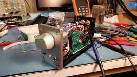
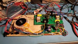
Some basic testing and fine tuning of the CCS circuits, had a few problems including a bit of operator error.. LOL (Forgot the CCS were opposite the channel the supply, oops. Should have marked the PCB)
Both channels pass clean signals, but I did not get beyond that.
I have uploaded an updated schematic with the component value changes.
The 6N6P draws significant grid current which I can see across the 1M input resistors which were intended to prevent popping with stepped attenuators that have break before make contacts. I do plan to use a fairly low resistance attenuator, but I may either need to select tubes or AC couple to the pot which I had not planned on doing. We shall see.
Attachments
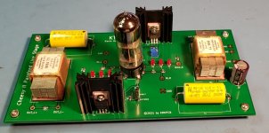
Some progress. Replaced the 10M45S with DN2540, basically equivalent performance.
Combinations that work. (Upper/lower)
10M45S/DN2540
DN2540/DN2540
IXPT08N50D2/DN2540
No significant changes in distortion or frequency response. I did not evaluate PSRR
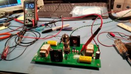
Investigating a resonance in the LL1930 at 20kHz. It's basically flat within 0.1dB from 20Hz - 15kHz, -1dB 18kHz, -3dB @ 20kHz, and above 24kHz is within 0.1dB to 30kHz, very odd. The behavior is identical on both channels and the amplifier stage is ruler flat.
Distortion performance is good, under 0.01% at 4Vrms from 50Hz - 10kHz the highest frequency I measured. (Amber 3501A)
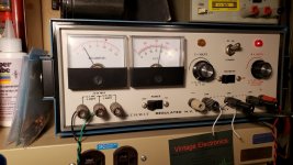
Getting power transformers is problematic. I am currently using a 200V/200V Antek which with a 6CA4 provides about 248VDC @ 30mA load. Plan is to raise the B+ to between 260V - 270V to provide a little more headroom for the CCS.
Boosted one 6.3V winding to 9V to provide headroom for the filament regulator. (14 turns of 18awg scramble wound on the toroid.
Combinations that work. (Upper/lower)
10M45S/DN2540
DN2540/DN2540
IXPT08N50D2/DN2540
No significant changes in distortion or frequency response. I did not evaluate PSRR
Investigating a resonance in the LL1930 at 20kHz. It's basically flat within 0.1dB from 20Hz - 15kHz, -1dB 18kHz, -3dB @ 20kHz, and above 24kHz is within 0.1dB to 30kHz, very odd. The behavior is identical on both channels and the amplifier stage is ruler flat.
Distortion performance is good, under 0.01% at 4Vrms from 50Hz - 10kHz the highest frequency I measured. (Amber 3501A)
Getting power transformers is problematic. I am currently using a 200V/200V Antek which with a 6CA4 provides about 248VDC @ 30mA load. Plan is to raise the B+ to between 260V - 270V to provide a little more headroom for the CCS.
Boosted one 6.3V winding to 9V to provide headroom for the filament regulator. (14 turns of 18awg scramble wound on the toroid.
Attachments
- Home
- Amplifiers
- Tubes / Valves
- A Stereo 6N6P Hybrid Line stage w/Parafeed Output Transformer