Hello!
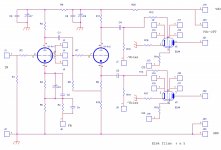
This is the last circuit I have developped around a push-pull of EL84.
The intention was to make a simply solution with a very good OT trafo.
In attach the schematic: it use a 6922 with the first section at gain and the second as cathodyna.
Then the output stage with fixed bias and a pentode connection ( my preferred).
The OT trafo is a double C core, laminated 0,1 mm, with 39:1 ratio.
The secondary is one fixed at 6 ohm nominal; the ratio is very high this because the intention was to fix the bias point in full class A until the max power.
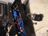
The second image is the proto of the OT trafo and it is possible to see one chassis this because the entire project is a mono amp so there are two chassis.
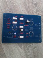
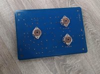
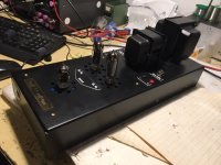
The third photo is the pcb with all components on board included the tubes.
At the test the output power is 10 w.
The Vdc is 300 volt and bias current is 40 mA each 84; the filter caps are 1000 uF total.
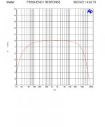
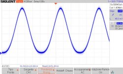
The diagram of the freq. answer is without feedback that in this project is 9 dB. The power is 1 watt/8 ohm.
At -3dB the cirve is good; 15 Hz to 85 kHz
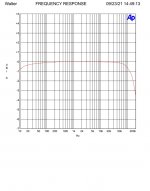
The other diagram is the response with feedback; - 1 dB at 10 Hz and 120 kHz ( around).
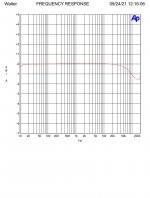
The third response is with a 0,22 uF in parallel to 8 ohm; also a good response.
The feedback is applied without any compensation cap and this is a good results.
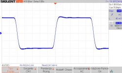
The lasts are the wave taken at the 1 ohm resistor of the 84 so it show is this circuit works in class A.
One is at 1 watt, the other is around 10 watt, close to the switch in AB.
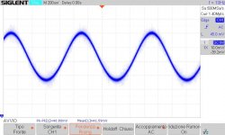
Last is the square wave 20 kHz, a good results ( I have taken other screenshot at differetn frequencies, always fine).
NOTE: this is a project Simulation FREE!! and Solid state FREE!! ( there is only the diode bridges)
")
Walter
This is the last circuit I have developped around a push-pull of EL84.
The intention was to make a simply solution with a very good OT trafo.
In attach the schematic: it use a 6922 with the first section at gain and the second as cathodyna.
Then the output stage with fixed bias and a pentode connection ( my preferred).
The OT trafo is a double C core, laminated 0,1 mm, with 39:1 ratio.
The secondary is one fixed at 6 ohm nominal; the ratio is very high this because the intention was to fix the bias point in full class A until the max power.
The second image is the proto of the OT trafo and it is possible to see one chassis this because the entire project is a mono amp so there are two chassis.
The third photo is the pcb with all components on board included the tubes.
At the test the output power is 10 w.
The Vdc is 300 volt and bias current is 40 mA each 84; the filter caps are 1000 uF total.
The diagram of the freq. answer is without feedback that in this project is 9 dB. The power is 1 watt/8 ohm.
At -3dB the cirve is good; 15 Hz to 85 kHz
The other diagram is the response with feedback; - 1 dB at 10 Hz and 120 kHz ( around).
The third response is with a 0,22 uF in parallel to 8 ohm; also a good response.
The feedback is applied without any compensation cap and this is a good results.
The lasts are the wave taken at the 1 ohm resistor of the 84 so it show is this circuit works in class A.
One is at 1 watt, the other is around 10 watt, close to the switch in AB.
Last is the square wave 20 kHz, a good results ( I have taken other screenshot at differetn frequencies, always fine).
NOTE: this is a project Simulation FREE!! and Solid state FREE!! ( there is only the diode bridges)
Walter
Attachments
-
 EL84_PP_schema.jpg245 KB · Views: 1,163
 -
 IMG_1164.JPG116.2 KB · Views: 1,147
 -
 EL84-PP_board.jpg444.1 KB · Views: 928
 -
 EL84-PP_board_2.jpg456.3 KB · Views: 896
 -
 EL84PP_risp_1w_8ohm_noFB.jpg122.6 KB · Views: 911
 -
 EL84PP_risp_1w_8ohm_9dB_FB.jpg121.9 KB · Views: 322
 -
 EL84PP_risp_1w_8ohm_9dB_FB+0,22uF.jpg124.9 KB · Views: 272
 -
 EL84PP-1w_classA.jpg49 KB · Views: 293
 -
 EL84PP-10w_fine_classA.jpg50.8 KB · Views: 255
 -
 EL84PP_140mVin_square_20kHz.jpg43.3 KB · Views: 480
waltube,
Congratulations,
Looks great!
I bet it sounds great too!
With a square wave that looks that good, with only a resistor for negative feedback and no comp cap across it . . .
That means the output transformer is Superb.
i would like to have a pair of those transformers, and 'matching' end bells.
Too expensive, especially with shipping.
Last edited:
to huggy
the pcb are arriving soon.
They cost 25eu. each + p&p
to brimax
I know very well the Leak that is a reference , but also other stuff.
Due the OT trafo with an high ratio I lost just few power ( 8 ohm resistive load) but it is capable to drive complex loudspeaker with a good efficency.
The sound seem to be very complete from bass to high with more "life" respect the Leak (p.e.)
to Kevinkr
The OT is very good stuff as the test lab says.
The little company who wound thse types of trafo use a beautiful machine comes from a hiend brand in Switzerland; I consider it is the best machine ( it is old ) to wound perfectly the bobbin. This is one of the major step I have seen.
Also the C core 0,1mm laminated helps. ( I use only C core on OT trafo)
I have ready also a s.e. for 300B and is coming a p-p for EL34/KT88
The costs are not low ( also because the numbers of production are not high)
All OT for p-p are always with one single tap on secondary and no UL connection ( only under request); in my opinion the tetrode/pentode connection is more exiciting.
I am preparing also a internet page to list the stuff with all real test lab.
With a help of my friend in Audioelettronica
Walter
Last edited:
You say the response -3dB is 15Hz for the low frequency but in my opinion, and a lot other technician* is far to high.Hello!
This is the last circuit I have developped around a push-pull of EL84.
The intention was to make a simply solution with a very good OT trafo.
In attach the schematic: it use a 6922 with the first section at gain and the second as cathodyna.
Then the output stage with fixed bias and a pentode connection ( my preferred).
The OT trafo is a double C core, laminated 0,1 mm, with 39:1 ratio.
The secondary is one fixed at 6 ohm nominal; the ratio is very high this because the intention was to fix the bias point in full class A until the max power.
The second image is the proto of the OT trafo and it is possible to see one chassis this because the entire project is a mono amp so there are two chassis.
The third photo is the pcb with all components on board included the tubes.
At the test the output power is 10 w.
The Vdc is 300 volt and bias current is 40 mA each 84; the filter caps are 1000 uF total.
The diagram of the freq. answer is without feedback that in this project is 9 dB. The power is 1 watt/8 ohm.
At -3dB the cirve is good; 15 Hz to 85 kHz
The other diagram is the response with feedback; - 1 dB at 10 Hz and 120 kHz ( around).
The third response is with a 0,22 uF in parallel to 8 ohm; also a good response.
The feedback is applied without any compensation cap and this is a good results.
The lasts are the wave taken at the 1 ohm resistor of the 84 so it show is this circuit works in class A.
One is at 1 watt, the other is around 10 watt, close to the switch in AB.
Last is the square wave 20 kHz, a good results ( I have taken other screenshot at differetn frequencies, always fine).
NOTE: this is a project Simulation FREE!! and Solid state FREE!! ( there is only the diode bridges)
Walter
A push-pull transformer should be easely below 5Hz otherwise the induction is far to less and so the transformer has not the right design.
* see radiotron designers handbook
- Home
- Amplifiers
- Tubes / Valves
- EL84PP, a simply circuit