> A choke in parallel with a resistor?
Of course. IRL probably a transformer, but that's not the tube-guy's problem.
> No value is given for the inductor.
No value given for frequency response, either, right? Again, this is not the tube guy's problem. At Philips there could be a different person for every detail. In small outfits, one person many hats.
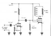
This tube was intended for car radios, which tend not to use field coil type speakers. This is either a poor way of showing an 800 ohm OPT primary or an 800 ohm speaker. It is also possible that a low DCR choke was placed across an 800 ohm speaker to shunt most of the DC current around the speaker.
These tubes existed in the late 50's / early 60's for a short time. The big fat TO-36 germanium transistor took over the output duties in car radios a year or three before the whole radio became solid state.
Beware the low plate voltage specs in these space charge tubes. Some will survive 90+ volts, some go into runaway long before that.
It is a triode with space charge tetrode. I interpret it figuratively as a transformer primary with a reflected load impedance of 800 ohms, with an RP of 480 ohms and up to 40mA of plate current you could perhaps get 100mW or so of output power?
Not sure how that choke it could be a field coil as it would have audio across it.
The only tube car radio I ever looked at I think used a 12AL8 to drive a transistorized output stage, but it was at least 4 decades ago and I remember none of the details. (There was at least 1 audio transformer in it.)
Field coils were used in car radio; brother's 1941 Plymouth. They did go permanent magnet ASAP because battery drain was a real concern.
The datasheet clearly shows 40mA at large distortion. While sold as "tetrode", input is at G1, so it is really a triode with a very hungry cathode. Heater power is more than a 6V6 which would make 100X the power (at 50X plate voltage) and cathode current is 10X plate current to loosen-up as many electrons as possible.
The circuit is *exactly* how you would test the *tube*. A choke to carry the DC current. A resistor to absorb the audio power.
The "load" here would be 10:1 transformer to the base of a 2N301 or similar transistor, working SE for 2W-4W final output to a loudspeaker.
At Philips there could be a different person for every detail. In small outfits, one person many hats.
Is there a connection between the 12AL8 and Philips? Or is this just a manner of speech?
The 12AL8 was developed by Tung-Sol (source: Radio Bulletin, April 1957, page 280 / https://nvhrbiblio.nl/biblio/tijdschrift/Radio%20Bulletin/1957/Radio%20Bulletin%201957-04-OCR.pdf). The 12AL8 is not on the Philips Factory Valve Codes list but probably this list is not 100% complete.
Attachments
That.The "load" here would be 10:1 transformer to the base of a 2N301 or similar transistor, working SE for 2W-4W final output to a loudspeaker.
Plus datasheet states:
"the tetrode section is intended for use as an audio power amplifier driver."
Sounds quite clear to me

The real load is transformer primary *OR* it´s a choke load, which generates TWICE the Vpp swing vailable from a simple resistive load, and the 800 ohm resistor probably tames the wild load impedance swings.
That.
Plus datasheet states:
Sounds quite clear to me
A cunning plan of deception
On this page you can find equipment in which the 12AL8 was used: 12AL8, Tube 12AL8; Rohre 12AL8 ID3809, Triode-Tetrode
I downloaded the schematics of three car radios (for non-members there is a limit of three downloads per day). In all three the 12AL8 is not being used for audio but as a relay driver.
Looking at some of the rest of the schematics I get the impression that the 12AL8 is being used as a relay driver there too (but the schematics are very small so it is difficult to be sure).
Attachments
Last edited:
The tetrode section of the 12AL8 is similar to the 12R5. I used to get scrap radios from an auto junkyard as a kid in the early 60's and attempt to build audio devices with their parts. The really old "junk" that they threw out used real tubes and vibrator power supplies.
These were mostly early crude guitar amps with more THD than raw power. I had better luck with part from dead TV sets. Some of them were actually loud AND clean. My SS stuff was one or the other.
The big hunk of germanium on a heat sink was somewhat useful as a class A audio amp. The 12R5 lived about 2 minutes on rectified wall outlet (about 125 volts with a tube rectifier and a 110 volt outlet. I did not understand the put B+ on G1 and drive G2 technology, so I just wired them up like a normal tube. Some would live for a while on two 45 volt batteries in series.
I decided long ago that space charge tubes were useless even for portable battery powered things due to their huge heater requirements. That along with a positive voltage on G1 was required to get enough emission for a few milliwatts of output power.
Best low power consumption tube amp I made so far used two 6AK6's in push pull for about 3 watts in near class B. It was a tiny guitar amp that ran from a 7.2 volt NiCad from an RC car. A step up boost converter made B+ that was about 170 volts at idle and about 150 volts when driven well into clipping.
The base of those old germanium transistors is a pretty low impedance so a step down transformer was often used to drive them. I used the speaker output of a Birnbach 1 watt transistor amp from Lafayette Radio Electronics to drive them.
The Birnbach used an OPT fed by a push pull pair of germanium transistors. I used the OPT from the radio that the transistors came from in my 1960's DIY amp. I believe the OPT was a low ratio step up design.
The DIY amp was way louder than the 1 watt amp by itself when running on 3 six volt lantern batteries in series. 4 would kill the transistor.
The very first SS amp I made (mid/late 60´s) was the output stage of a car radio, with a single TO3 germanium transistor (guess it was an AZ15 or maybe an OC23?)
Argentina was also a "Philips Country" and we had our own branch, complete with Factory and Brand (FAPESA, same as Mullard, Miniwatt, etc. in other Countries)
It run finger blistering hot (how did I find that? ) at 12V (car battery) 1A idle current.
After burning 2 in a row (they were expensive for me) shop assistant asked about the heatsink I was using.
"Heat .... what?"
And it used the exact same load type as the OP´s, only the SS version: choke loaded collector with speaker in parallel.
I would also call it "paraphase", and in that case no output/coupling really needed; 90/95% of collector current went through the choke because of its low DCR compared to voice coil.
Argentina was also a "Philips Country" and we had our own branch, complete with Factory and Brand (FAPESA, same as Mullard, Miniwatt, etc. in other Countries)
It run finger blistering hot (how did I find that?
) at 12V (car battery) 1A idle current.After burning 2 in a row (they were expensive for me) shop assistant asked about the heatsink I was using.
"Heat .... what?"
And it used the exact same load type as the OP´s, only the SS version: choke loaded collector with speaker in parallel.
I would also call it "paraphase", and in that case no output/coupling really needed; 90/95% of collector current went through the choke because of its low DCR compared to voice coil.
> The tetrode section of the 12AL8 is similar to the 12R5.
https://worldradiohistory.com/hd2/I.../50s/57/Electronics-1957-02-OCR-Page-0146.pdf
And while this thread questions its audio use, TungSol boasts of relay control and mentions audio only in passing.
There's only a slim year+ when an audio driver tube made sense compared to a driver transistor. Relay control lasted longer because the drive was the readio detector and a tube could give 3+Meg loading where leaky Germanium struggled to hit 100K.
Attachments
Do you have a source for this? Or an example of this tube being used like that?
Why would Tung-Sol develop a tube for 800 Ohm loudspeakers which were only made by Philips and (as far as I know) were hardly solded/used in the USA?
Besides that: The power output is only 40 mW (see post #9 and/or the datasheet)
Why would Tung-Sol develop a tube for 800 Ohm loudspeakers which were only made by Philips and (as far as I know) were hardly solded/used in the USA?
Besides that: The power output is only 40 mW (see post #9 and/or the datasheet)
Last edited:
- Home
- Amplifiers
- Tubes / Valves
- What the heck is this load?