I want to experiment with valve pre-amp circuits using ECC83 and EF86 tubes. I have all the prerequisites for a full valve amplifier I found on eBay.
Can anyone suggest some resources that emphasise how to construct valve amplifiers for experimentation rather than constructing a final product?
For circuit development I want an approach that is
Now I could just re-wire the valve amp inplace.
But…
I think it is a sensible approach to build a PCB power supply for HT, screens and heaters. The power transformer can connect to this board which just provides DC for the rest of the project. I can imaging this minimising risk, restricting all the high voltage to well labelled and isolated wires.
Which leaves the preamp…
Some ideas:
But I’m interested in knowing what approaches you use, what’s works and what does not.
Can anyone suggest some resources that emphasise how to construct valve amplifiers for experimentation rather than constructing a final product?
For circuit development I want an approach that is
- Safe
- Easy to follow/read the circuit
- Quick to modify the circuit
Now I could just re-wire the valve amp inplace.
But…
I think it is a sensible approach to build a PCB power supply for HT, screens and heaters. The power transformer can connect to this board which just provides DC for the rest of the project. I can imaging this minimising risk, restricting all the high voltage to well labelled and isolated wires.
Which leaves the preamp…
Some ideas:
- Use an empty chassis and mount terminal strips
- Use typical breadboard, tube can be connected with PCB
- Re-usable PCB, from Valve Wizard ��*♂️ The Valve Wizard
- Others?
But I’m interested in knowing what approaches you use, what’s works and what does not.
Last edited by a moderator:
You might want to find a working heathkit IP-17 or eico bench power supply on ebay, this will give you variable B+ and bias as well as filament power. If breadboarding the amps power supply itself, its very good to have a variac and be able to bring up the transformer of your design slowly. But never breadboard directly from the variac because it is not isolated from mains. Always breadboard with the power transformer you intend on eventually using or something close, for isolation. Those small 2.54 mm spaced breadboards are kind of useless, when you push anything over 22 AWG wire into them the springs stretch out and stop springing. And many power resistors, big caps, etc use as high as 18 Awg, which wont even fit those. Pete Millet sells some tube socket breakout boards, you'll need several of those, that takes care of hooking to the tube pins. For the other parts I use some spring clips that take anywhere from 24 to 14 awg wire. You see many here Strapping it up with gator clip wires, you'll need those.
I am designing a tube breadboarding PCB with an array of these large spring clips now for myself. It is a 10 x 15 inch board similar to a regular breadboard but uses 5 pin rows of these giant spring clips, roomy. Be safe, have fun, double check wiring, apply voltage slowly.
I am designing a tube breadboarding PCB with an array of these large spring clips now for myself. It is a 10 x 15 inch board similar to a regular breadboard but uses 5 pin rows of these giant spring clips, roomy. Be safe, have fun, double check wiring, apply voltage slowly.
Here are a few sample options. If you make pcbs, you can design your own.
9-Pin Socketed Vacuum Tube Breakout Board (NEW) | eBay
Amphenol breadboard vacuum tube socket octal for | Etsy
9-pin breadboard / prototype tube socket for DIY experimenting | eBay
9-Pin Socketed Vacuum Tube Breakout Board (NEW) | eBay
Amphenol breadboard vacuum tube socket octal for | Etsy
9-pin breadboard / prototype tube socket for DIY experimenting | eBay
I think breadboard systems depend pretty heavily on your personal way of working, but somewhat axiomatic is : You can never have too many clip leads.
I prefer making my own of various lengths with more flexible silicone rubber insulation but this implies you're imagining yourself doing more than just one circuit in the future. If you're only going to be at it for this one project then cheap ones like THESE (that you may have to fix the connections on as soon as they're out of the package) make more sense.
Also suggest that if you go with a pre-made board as linked above by Rayma, take care to get one that has more than one input per tube pin. For example, the ones from pmillett in the bottom link posted by Rayma have two per pin. He's also a forum contributor and IME worth supporting.
If you want to do something good for experiments in the future I think it's worth taking a look at what Tubelab_com did, HERE. It involves some prep work but looks like it would make it pretty convenient to just throw stuff together whenever you have the inclination. Well, that's what it LOOKS like to me , anyway.
Ditto on the above recommendations from Windcrest77 above for Variac fed power transformer powered linear supply and for a bench supply from Heath , Schlumberger, or Eico etc.
If you're into it for the longer haul and want to put a breadboard in the living space to listen to for a while before committing to a finished build you can make a box with power and connectors that will take your circuit on a piece of plywood . . . . . . making it safe for those not involved in your exploration but easy for you to swap circuits on. I made some out of sheet steel with perforated top and bottom for ventilation and cool "Ooh, there's a light inside" factor as soon as I realized I was going to be at it for a while and they've proven to be extremely useful. Some of the old Eico or other chassis might be good for that as well. I've also used old PC cases with shelves on drawer slides for the same thing.
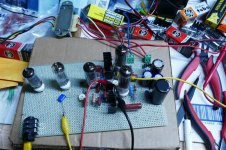
My experimental valve circuits were never safe, so they don't meet your first requirement. I once built a high-voltage amplifier with 2660 V supply on two very long pertinax perfboards without copper. I probably made some holes larger for the pins of the (PCB-type) valve holders. I also used perfboard without copper for some other circuits. For my valve DAC, I needed a -300 V plane and used single-sided copper-clad board with some holes drilled in it for valve holders intended for chassis mounting, see the attached photo. The supply is on the perfboard in the front.
Attachments
Last edited:
I have a different approach to this. Having been brought up on Meccano I love screwing things together so I decided 10 years ago to use a modular system of top plates and screw them down into 19" rack mount subframe parts like horizontal rails and threaded inserts. Over the years I've built up quite a collection of modules on 100, 70 and 50mm wide plates, all with a depth of 275mm. So I can construct a new project using mainly pre-existing parts. Downside is lots of screw holes when re-purposing plates but I can live with that. Upside is each plate is so small and easy to work on and finish before screwing into the chassis.
Attachments
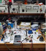
I'd add its good to have 4 or 5 cheap but accurate digital multimeters as well as one good Fluke. This way you can see many voltages at once as you power up a newly strapped circuit slowly, if something looks out of whack as you turn up the voltage you can back off right away. A supply of 1 ohm 3 watt resistors is handy too, then drop those in various places to get/sense direct reading of a current as well in real time.
I encourage the use of LTSpice and PSUDII modeling whenever possible. It saves a LOT of trial and error breadboarding. Once I had modeled all the circuits of my 833 amps multiple times I went straight into my build, and it was successful the first time, with a few minor adjustments. The great thing about modeling is you can do really stupid things and not annihilate expensive components or start fires.
Hi everyone,
This is such a fantastic response! Thanks so much. I’ve really got some good ideas. The warning about using standards breadboards is taken on board. I really like Tube Lab’s approach and also the approach of having a few of those valve PCB of PMillett; I could imagine using those for the tubes and a mix of PCB and tag board of the rest. And noted about getting a variac.
I have a Spice mode about 50% complete, I definitely plan on using that to debug the fundamentals, and then once happy will shift to prototyping. I just wanted to be ready to prototype when the simulation phase is done.
These PCBs for tube sockets are quite handy ....
Prototype board
I bought a bunch, and fitted 2 with 7 pin sockets, 4 with noval, and 4 with octal. A proper, isolated power supply is critical, I think, since the operating points in the amplifier need to be refined, and then the power supply designed to match those points. That probably means focussing on only one channel in the prototyping stage.
I really admire the approach of andyjevans, above. That would be my ideal solution, but life has recently got in the way of having the time required to invest in a long term solution.
A preamp is not the easiest project to breadboard, if I have followed others experiences closely enough on this site. Placement of the components and good electronic practice (heaters, grounding) are important to a preamp, so a more rigourous solution is probably required to derive good information from the build.
I´ve been prototyping Tube stuff since the mid 60´s, always used the classic bread board method: a serving tray sized piece of wood (you´ll compact layout later, now you need space) with nails all over it, brass preferred if possible but if not, iron works fine, if you have a hot classic 60/100W iron (no 30W snowflake types here).
Tinned solid wire makes ground and various +V bars.
You do NOT clip component leads, as they are reused over and over.
Tube sockets are mounted along an L bent aluminum strip and wires go back and forth.
I make Guitar Amps and a few times the breadboard monstrosities were used live, on stage, go figure.
Valve circuits can be breadboarded just like any other: just wire the tube sockets with solid wire, to allow the insertion into a regular breadboard.
An example here:
Having some fun supercharging a E/PCL82 amplifier
Of course, it is not suitable for voltages >1kV, VHF/UHF circuits, etc.
For a preamp, it can be useable as long as you don't focus on S/N ratio, low THD levels, etc. : just place a piece of virgin copper-clad under the breadboard (and ground it, obviously).
For the supplies, there are many examples on the forum. I have described a few myself, including Elektria, see my signature.
I´ve been prototyping Tube stuff since the mid 60´s, always used the classic bread board method: a serving tray sized piece of wood (you´ll compact layout later, now you need space) with nails all over it, brass preferred if possible but if not, iron works fine, if you have a hot classic 60/100W iron (no 30W snowflake types here).
Tinned solid wire makes ground and various +V bars.
You do NOT clip component leads, as they are reused over and over.
Tube sockets are mounted along an L bent aluminum strip and wires go back and forth.
I make Guitar Amps and a few times the breadboard monstrosities were used live, on stage, go figure.
Would love to see a photo of this to get a feel for it. That seems really pragmatic, I like that a lot. Do you have blog or website that shows behind the scenes stuff?
Hi Elvee,
I didn’t understand your Elekria design what’s input power does it need? To you input HT from a transformer and it regulates it down to a variable voltage?
Also thanks for the correction on breadboards, I quite like this as an option. It seems easy to get started, just need to purchase some PCB for mounting tubes…. and build a power supply!
Hi Boyfarrell,
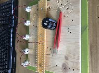
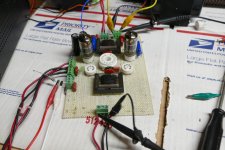
I'm right now breadboarding my SEPP EL84 on separate wood "chassis" - to check all those voltages before making final prototype - It is totally not SAFE!
You need to control yourself and be extremely careful were you put your hands while measuring and while resting alike!
I'm right now breadboarding my SEPP EL84 on separate wood "chassis" - to check all those voltages before making final prototype - It is totally not SAFE!
You need to control yourself and be extremely careful were you put your hands while measuring and while resting alike!
Attachments
I´ve been prototyping Tube stuff since the mid 60´s, always used the classic bread board method: a serving tray sized piece of wood (you´ll compact layout later, now you need space) with nails all over it, brass preferred if possible but if not, iron works fine, if you have a hot classic 60/100W iron (no 30W snowflake types here).
Tinned solid wire makes ground and various +V bars.
You do NOT clip component leads, as they are reused over and over.
Tube sockets are mounted along an L bent aluminum strip and wires go back and forth.
I make Guitar Amps and a few times the breadboard monstrosities were used live, on stage, go figure.
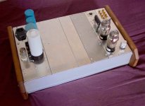
This is where I started in the early / mid 1960's as a kid making tube stuff with parts salvaged from scrap TV's and radios. I used a pine wood board as the chassis.
The connection points were sometimes terminal strips ripped from old TV's, sometimes brass furniture tacks used for upholstery in the 1950's, and sometimes just the heads of brass screws screwed into the wood. As stated a big soldering iron or the trusty WEN or Weller soldering gun is needed to heat them.
I soldered a short piece of wire to each pin on a tube socket, then simply screwed the socket to the board with wood screws. Sheetrock screws would be a better choice today, but they were not common in the early 60's. Each wire was soldered to it's own brass tack after the socket was screwed to the board. Due to availability at that time almost all of my DIY stuff used octal tubes.
Heater, B+ and ground were run across the back of the board with stripped #12 or #14 house wire. Stick one end of the wire in a vise, grab the other with pliers, and stretch it just a little. After that it will lie perfectly straight and flat and can be bent as needed.
I mounted pots to a piece of metal angle and put it on the front of the breadboard.
About 30 years ago I made a recreation of my first DIY guitar amp, built when I was about 12 years old. It used a 6SJ7 driving a 6BQ6GT powered by a 5Y3 and a transformer ripped from an old radio. The OPT was the vertical sweep transformer from a TV. Unfortunately it was lost during a hasty move. I had three weeks to clean everything out of my house in Florida where I had lived for 37 years. Somehow the white plastic pegboard "Tubelab III" made the trip, but the box full of modules for it is gone.
I actually sold a few of my DIY amps made this way. They were ugly unfinished pine boxes with window screen for grill cloth, but to my young ears they sounded pretty good. It was the 60's in Florida and I really wanted reverb to play surf music, but tanks could not be found in the trash.....yet. I remember selling one of the amps to the older brother of a classmate for $5, a big deal to a kid in the 60's.
Seven or eight years later I was the service tech at an Olson's Electronics store near the University of Miami. A student from the UM School of Music walked into the store with that amp wanting it repaired. The counter sales person basically told him that it could not be fixed, but I spotted it from the rear of the store, ran out to the counter and told the customer that I could fix it, and would do so for free!
The amp had been found in a corner of a closet in the music lab. It needed a new filter cap and a general resoldering, but worked pretty good. That repair job got me access to their music lab. They had a Mini Moog and a brand new ARP 2600. I seemed to understand what the controls on the 2600 did better than their instructor, so I kept getting sales pitches to come to their very expensive school so that I could become another starving musician or music teacher. A short time later I accepted a job at Motorola 30 miles away and I never saw the music lab again. I stayed at Motorola for 41 years, so I guess I made the right choice.
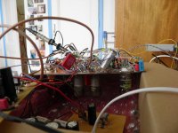
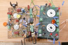
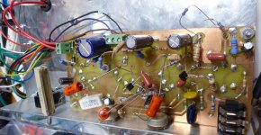
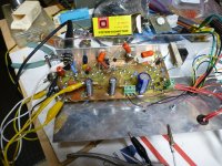
I have been looking for a better way to rebuild and improve the Tubelab breadboarding system and collected some ideas and parts, but haven't started building anything yet. For now most of my experiments look like flying messes of parts built on perf board, or on top of an old failed PC board design.
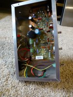
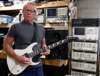
The flying lead solid state parts and clip leads leading to several pots pictures were part of the process of an all tube guitar amp built for the Hundred Buck Amp Challenge being modified into an amp that I really liked and still use today. The resulting design was made into a new PC board design, and fitted into a proper small chassis. It is seen sitting on top of the speaker cabinet. The remains of the original cab be seen on top of the spectrum analyzer behind my head and to the right of my ear. It served its useful purpose and was tossed into the "box of dead projects" where it will be robbed for parts, or used as the basis for another experiment some day.
Attachments
-
 P3990421_x.jpg806.4 KB · Views: 188
 -
 P3990310_x.jpg823.8 KB · Views: 251
 -
 P3990293_x.jpg633.3 KB · Views: 360
 -
 P3730055_x.jpg202.3 KB · Views: 281
 -
 AmpFurball_x.jpg707.3 KB · Views: 170
 -
 P1050281_x.jpg932.3 KB · Views: 171
 -
 Chassis_1_x.jpg601 KB · Views: 158
 -
 Chassis_4_x.jpg387.8 KB · Views: 157
 -
 NewGuitar_x.jpg862.3 KB · Views: 182
Last edited:
It is totally not SAFE!
 LOL
LOLI Love the pragmatism of this… maybe I am over thinking things … I would like to at least attempt to minimise some risk.
Hey TubeLab,
That’s such a cool story, I would love to have even 10% of your knowledge and experience!
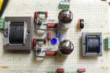
Those photos really help me visualise ways of doing this. They look remarkably neat! This all makes me think I’m over thinking things and I should just stay cheap and pragmatically.
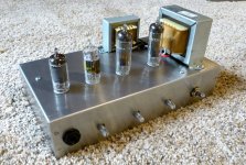
A question: looking at photos 1 and 2, how do you know that the tube sockets could pin mount directly into holes on your board? Or did you mount them in another way? Did you mount the transformer just by cutting out a hole?
That’s such a cool story, I would love to have even 10% of your knowledge and experience!
Those photos really help me visualise ways of doing this. They look remarkably neat! This all makes me think I’m over thinking things and I should just stay cheap and pragmatically.
A question: looking at photos 1 and 2, how do you know that the tube sockets could pin mount directly into holes on your board? Or did you mount them in another way? Did you mount the transformer just by cutting out a hole?
This is one way to mount tubes on breadboard. I believe you'll need a schematic which is regularly updated and a PCB layout for final prototype. In making this possible my prototype is done on insulation board, eyelets holes drill according to footprint on the PCB layout. ExpressPCB is the software you can use.
Vacuum Tube SPICE Models
Vacuum Tube SPICE Models
Vacuum Tube SPICE Models
Vacuum Tube SPICE Models
Last edited:
- Home
- Amplifiers
- Tubes / Valves
- How do you develop/breadboard valve amplifier circuits?