What is the method a beginner can use to properly spec and wire power toroid(s) for any given PP output stage impedance?
I have an LCR meter, is it as simple as loading the secondary to 4, 6, 8, 300 ohms, (whatever impedance my speaker is), and measuring what primary impedance I wind up with for a variety of stock power toroid's? Building up a list of power step down voltages (USA) that will work for various plate load cases 8K, 10K, 3.4K, 1.6K, 5K, etc?
I have 5V, 6V, 7V, 12V, etc. Antek sample toroid's in my stash now.
Schematics of projects you've done using power toroid's as OPT would help too.
Just trying to learn a repeatable method to ballpark-fit stock power toroid's for OPT usage, experimentally or using the limited specs from the mfg.
You want to use a mains transformer as an audio output transformer ---right ?
Regardless of some designs doing this please have a read of what design technicalities are involved in an actual audio output transformer -
https://www.jensen-transformers.com/wp-content/uploads/2014/08/Audio-Transformers-Chapter.pdf
Regardless of some designs doing this please have a read of what design technicalities are involved in an actual audio output transformer -
https://www.jensen-transformers.com/wp-content/uploads/2014/08/Audio-Transformers-Chapter.pdf
I've posted many times on this. Every amp I build and or sell uses toroid PTs as OPTs. They sound better, provide more power (lower loses) and cost less.
Use a pair per channel (4 per stereo amp) if you want bass.
For best results, use triode connected beam tubes like EL86 or EL500. Dual 6V secondaries will give you 3k:8R, 2k2:6R etc which works well for sweeps or other tubes that have current to give.
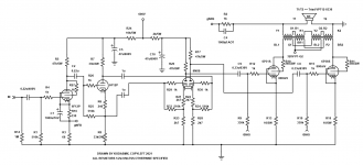
Here is an example using 6P 31S
R9 and R19 should be 100k for better LF stability, and R2 should be 2k for the same reason. I'd also run 60mA instead of 80mA (80mA for EL500, 100mA for EL519, 40mA for EL86 etc). The beauty of this is you can plug in almost any triode connected tube if you change the bias point.
Koda
Use a pair per channel (4 per stereo amp) if you want bass.
For best results, use triode connected beam tubes like EL86 or EL500. Dual 6V secondaries will give you 3k:8R, 2k2:6R etc which works well for sweeps or other tubes that have current to give.
Here is an example using 6P 31S
R9 and R19 should be 100k for better LF stability, and R2 should be 2k for the same reason. I'd also run 60mA instead of 80mA (80mA for EL500, 100mA for EL519, 40mA for EL86 etc). The beauty of this is you can plug in almost any triode connected tube if you change the bias point.
Koda
Attachments
Last edited:
Merlins example was about the worst possible use of a mains toroid, driven by high source impedance (pentodes) and trying for a ~10k primary, guaranteeing poor frequency response and low power output. Although was helped out by the low supply voltage. Of course, he would know this ")
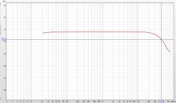
Like Koda says, they work well driven by a low source impedance (triode or triode connected pentode/beam tetrode), and low voltage/high current (low primary impedance). Attached is a spreadsheet to work out impedance and maximum power output based on primary and secondary voltages vs frequency. Also attached is frequency response at 10W for an amp I built using power toroid outputs. Could be better but I was fairly aggressive on the compensation for the negative feedback.
Like Koda says, they work well driven by a low source impedance (triode or triode connected pentode/beam tetrode), and low voltage/high current (low primary impedance). Attached is a spreadsheet to work out impedance and maximum power output based on primary and secondary voltages vs frequency. Also attached is frequency response at 10W for an amp I built using power toroid outputs. Could be better but I was fairly aggressive on the compensation for the negative feedback.
Attachments
The main consideration is keeping DC out of your toroidal, ie perfectly balanced current in each half of the PP pair. CCS are the best way to achieve this but Garter bias also works if your cathode voltage is fairly low (otherwise to wasteful).
As said, keep voltage low and current high and use a low rp final.
Smaller is better, I tend to go for 3-4x the anticipated wattage in VA rating. This will maximize primary inductance.
The primary windings will have a direction and you should try them in both directions and measure their response, this is because one direction will have much higher parasitic capacitances then the other and this will significantly effect the frequency response.
Ideal candidates for finals are EL86 and 6080's.
If you follow these guidances your results are likely to exceed anything a commercial OT can deliver for for less than a quarter of the cost. If you are prepared to spend big on commercial transformers Toroidals can be bettered.
Shoog
Last edited:
These topologies only work well in class A, but it will be the best watts you can get. Many people say that they hate PP designs when really what they are saying is they hate high gNFB class AB designs compared to class A SE designs. Most people have never heard a class A PP design so you can safely dismiss most of what they say on the subject.
Shoog
Shoog
It's worth pointing out that the sweet spot for a PT as OT is usually a primary impedance somewhere between 2k to 4k.
Since the maximum primary voltage of a PT is 240Vrms @ 50Hz, this means your output power is limited to less than 30 watts @ 50Hz before you hit saturation, or only 15 watts @ 25Hz (in practice even less).
KodaBMX shows how you can use two PTs which might allow you to squeeze twice the power through, but don't expect to be building any 100W monsters!
Very true MerlinB, if you look at the made for Output duty toroidals that are commercially available - they are massive in order to get response down to 10hz or lower. I can get power down to 10hz on my amps but they are carrying small power since I run very sensitive speakers.
However its a trade off when using power toroids, you need a big core to get more power handling but the bigger the core the lower the primary inductance - which is what you need for low frequency handling. The urge to go massive is the wrong approach, just big enough is correct and hence my 3-4x rule of thumb.
Shoog
Last edited:
KodaBMX shows how you can use two PTs which might allow you to squeeze twice the power through, but don't expect to be building any 100W monsters!
Not true - Using PPP trioded EL519 into a pair of 250VA VPT18-13800 I get 113W RMS @ 30Hz. The amp schematic is identical to the above but the output tubes are paralleled and the coils are configured to reflect 1k:6R.
Seriously, using two connected as I showed above gives better results than actual OPTs (Hammond 1650N), and DC balance is important but nowhere near as much as you'd think. A few mA mismatch doesn't matter at all.
Each coil is rated for 230V/50Hz. Connecting two like in my example make one 460V/50Hz or 230V/25Hz transformer. This is why 30Hz works just as well as 1kHz...
The amp above is available in PCB form, too. So far it supports about 150 different tube types.
Last edited:
I'm glad this question has come up!
Question:
- Let's say I already have a pair of Dynaco Z565 OPTs (approx. 8k p-p primary to 8,16 ohm secondary). That OPT is rated for 17W.
- Let's say I use the 8 ohm secondary tap to connect to a 4 ohm speaker, so the reflected load from the primary is now only 4k ohms (plate to plate).
- Let's say I want to use that OPT with a PP EL86-triode pair with 260V plate-cathode (300V B+) and 50mA plate current for each EL86 (which I believe with a 4k load will bias the EL86s into class A territory).
What, if any, advantages are there to using a toroid power transformer over using the Z565 audio OPT? Is it all about cost/performance or are there reasons a toroid is actually superior in this particular use scenario?
Thanks.
The trick is getting the reflected impedance high enough (and that includes the primary inductance). Bigger doesn’t help what is essentially a turns shortage. Koda’s trick of interleaving two in series to get higher impedance will work until the insulation between bifilar turns fails. At the power levels he works at using triode connected sweeps, B+ is somewhat limited - and that point hasn’t been reached yet or we’d be seeing pictures of flameouts. I’m not terribly sure where that point is myself so I haven’t been willing to put 600 volts between two halves of a 120/240 toroid to find out. Too bad 240/480 aren’t generally available or I would be snatching them up as quickly as the pocketbook will allow. I do find plenty of 480 volt EI’s, but they usually hum like crazy in normal operation so I doubt their performance as OPTs would be any good. Suffice it to say that at lower power levels there are solutions that work. You do have to live with the choices of primary impedance that you can get. And there is no easy way of making an amp with 4 and 8 ohm secondary taps. You’re stuck with one or the other - whichever you designed for.
I’ve been thinking about a couple of really BIG amps using the largest tube power toroids I can get my hands on and using them backwards. That is, with the 120V primary as an 8 ohm secondary. That requires a very high voltage rather than low. Lots of turns (for the power level). The AS15T950 will give 1k a-a at 4 ohms (2k at 8), and the AS8T800 gives 1400 at 8. Now you can work with crazy B+ without running out of magnetic headroom, and multiple hundred watts becomes a possibility. Experiments are not really far enough along yet to even see what the problems are, but the theory holds. Right now I’m off working on solid state amps that work on voltages normally associated with tubes, back burnered since 2009.
I’ve been thinking about a couple of really BIG amps using the largest tube power toroids I can get my hands on and using them backwards. That is, with the 120V primary as an 8 ohm secondary. That requires a very high voltage rather than low. Lots of turns (for the power level). The AS15T950 will give 1k a-a at 4 ohms (2k at 8), and the AS8T800 gives 1400 at 8. Now you can work with crazy B+ without running out of magnetic headroom, and multiple hundred watts becomes a possibility. Experiments are not really far enough along yet to even see what the problems are, but the theory holds. Right now I’m off working on solid state amps that work on voltages normally associated with tubes, back burnered since 2009.
Price and ease of availablity is literally the only advantage of using the PT. Actual performance will be much worse.What, if any, advantages are there to using a toroid power transformer over using the Z565 audio OPT?
Merlins example was about the worst possible use of a mains toroid, driven by high source impedance (pentodes) and trying for a ~10k primary, guaranteeing poor frequency response and low power output. Although was helped out by the low supply voltage. Of course, he would know this
Like Koda says, they work well driven by a low source impedance (triode or triode connected pentode/beam tetrode), and low voltage/high current (low primary impedance). Attached is a spreadsheet to work out impedance and maximum power output based on primary and secondary voltages vs frequency. Also attached is frequency response at 10W for an amp I built using power toroid outputs. Could be better but I was fairly aggressive on the compensation for the negative feedback.
Thanks! the formulas in this sheet are awesome, I'll be studying these numbers and how they relate. And all the other info so far too, not to end the topic though.
Last edited:
Price and ease of availablity is literally the only advantage of using the PT. Actual performance will be much worse.
i would tend to disagree with that, if you drive the toroidal with a low enough rp the bandwidth is easily out to 50Khz and distortion will be low. Those who have gone this path say it can sound better than the EI OT's they have used. Of course you need to make your choices to run with optimizing the toroidal but that not that difficult. i have never found the result subpar or disappointing. As I said before you have to spend big to get good performance out of an EI because they require lots of skill to make well - many are not made well. As an example a typical power toroidal will outperform an Edcor any day of the week.
The reason why toroidals make poor audio power transformers is because of their extreme bandwidth that lets lots of high frequency hash through the power supply.
Shoog
Last edited:
The transformers I use are hipot tested to 4kV. Not at all worried about it TBH. A primary to primary short would make a silence machine, a primary to secondary short would blow the fuse.
Those things will test 4kV between primary halves? I know they make that from primary to secondary - with enough tape in between it’s hard not to. When they purposely build a “1900VCT transformer” you know they are at least paying attention to it.
I do find plenty of 480 volt EI’s, but they usually hum like crazy in normal operation so I doubt their performance as OPTs would be any good.
EI power transformers have horribly low bandwidth, they wont even make it out to 10Khz. Thats what makes them good as Power transformers. This bandwidth issue is partly due to leakage inductance which is an intrinsic limitation of EI's and why building a good audio EI OT is so difficult.
Shoog
That spreadsheet is very good to have and relieves lazy people like me from doing the math for themselves. Thanks!
I guess the only way to settle this question would be to do an A-B comparison.
It looks like a 230V:6V 100VA power transformer should work as a push-pull OPT of about 5k:4.
Antek AS-1206 costs $21.60 each, weighs 3.3 lbs each.
https://www.antekinc.com/content/AS-1206.pdf
Does that look like a contender?
--
- Home
- Amplifiers
- Tubes / Valves
- Newbie question: Design techniques for using power toroid as OPT