

So it is possible to modulate your SMPS directly using the voltage feedback loop
 This is with a simple voltage source - next is to sim with a full valve front end.
The above has a high switching frequency (300kHz) but it's certainly possible. Obviously this needs addition work for safety and for providing a wave centred around 0 (a cap could do that short term). The controller has a natural maximum current limit in the current-sensor resistor but should have some safety devices.
I'm using my isolated 48V SMPS boost controller but the same could be done with a buck converter, flyback, full/half bridge or any SMPS configuration.
This is essentially a hybrid- the back end signal does go through the PWM controller and the resulting mosfet switching is then altered to recreate the signal.
Oh and it works with 1.2V output just as well..

Last edited:
I'll have chance to add add a valve to the simulation later tonight.


As I said - there's a safety element that needs a think through. One option would be to simply hard set the voltage and impose the signal onto it. The important point is that the feedback is the mechanism the the IC sees the voltage so this needs to override the superimposed output. It works without having the feedback and vout directly connected but then it's simply assuming the correct output.
Possibly I'll get stoned for using the term 'modulated' loosely You could use a magnetic amp to replace the mosfet and then run the control switching through a valve.. however I think that's going too far.
As I said - there's a safety element that needs a think through. One option would be to simply hard set the voltage and impose the signal onto it. The important point is that the feedback is the mechanism the the IC sees the voltage so this needs to override the superimposed output. It works without having the feedback and vout directly connected but then it's simply assuming the correct output.
Possibly I'll get stoned for using the term 'modulated' loosely
You could use a magnetic amp to replace the mosfet and then run the control switching through a valve.. however I think that's going too far.
Last edited:
Back in 1975 through 1984 I worked in the calibration lab at Motorola. For some of those years I ran factory floor support, which is a fancy way of saying that I was a Mr. Fixit for most everything that broke down in a large factory making police walkie talkies. Old timer ham radio operators may remember the HT220. My "crash cart" contained 5AR4's, 12AX7's and 6DQ6's. Why?
Even in this "modern" factory some stuff still ran on vacuum tubes. Sure there was solid state stuff available, but much of it went bonkers when you keyed up a 5 watt walkie talkie near it. We made and used walkie talkies, someone somewhere in that factory was transmitting at any given moment, usually several someones.
The 5AR4's were the rectifier tube in the HP200AB audio oscillator. It was the only tube in the unit that went bad. The factory supplied tube was an Amperex bugle boy! The 12AX7's were for the RCA Senior Voltohmist VTVM. It rarely went bad. The 6DQ6's were for the SMPS in the Tektronix 504 scope. I changed one of them every week or two. Again, the only tube in the scope that went bad.
Yes, the 1960 vintage Tek scope had a SMPS powered by a TV sweep tube (the 6DQ6) and a triode / pentode, a 6BL8. Sometime in the early 80's the old Teks were swapped out for Hitachi V151's.
The SMPS page out of the manual is enclosed.
The entire manual can be downloaded here:
Bama Manual Archive
There is a brief explanation of the power supply on page 4-6.
Attachments
I think that in 1960, there were not any high voltage bipolar transistors (PNP or NPN) that could switch a transformer primary that had 500V B+. Not even long enough to set the High Voltage adjustment.
A real good reason to use the 6DQ6, even if it did fail after a while. At least you could set the amplitude of the high voltage.
And the switching MOSFETs of today were not even a dream in the engineers mind.
A real good reason to use the 6DQ6, even if it did fail after a while. At least you could set the amplitude of the high voltage.
And the switching MOSFETs of today were not even a dream in the engineers mind.
A real good reason to use the 6DQ6, even if it did fail after a while. At least you could set the amplitude of the high voltage.
That factory ran 24/7. Nothing was ever turned off. Still the 5AR4 in the audio generators lasted 3 to 5 years, and the 6DQ6's maybe a bit longer. We just had a LOT of that equipment.
Hi Nick, still not sure what you are trying to do, and I am familiar with (love) the UC2843 family...., I see no tube in you cct, are you planning to use one instead of the mosfet?
I'm trying to add current capability to a OTL output with minimal the additional tubes, or simply use a mosfet follower (or BJT using current).
I've looked at magnetic amps, it could work but probably needs more current than a driver valve would realistically provide so the next step would be looking at SMPS. I remember back in the day went Millennium TaCT essentially made an SMPS with audio. Class D is probably closer to this now, but what if - a valve output section drove a power supply (optional if this was made of valves itself) to provide the final audio drive. Could it be possible?
Sorry if my random explorations annoy people
For now the focus is simply getting my little amp working (which is in the pipeline) but I'm stuck with Richard Feynmanesque curiosity but not the intelligence..Just use a tube-Mosfet Darlington circuit (with lower Voltage for the Mosfet) or a tube-Mosfet Complex Fdbk Pair. All tube OTLs just turn into space heaters.
There is also the Kulish circuit that can remove the distortion of the high current driver device. (search in tube and SS threads, its a feed-forward scheme)
Then as I mentioned in your thread:
https://www.diyaudio.com/forums/tubes-valves/371254-harmonic-cancellation-transformers-new-post.html
The common distortions of OTs can readily be removed for conventional tube amps for half way decent OTs. There is really no reason whatsoever to build an OTL space heater. These problems have all been solved already, just no one listens. They prefer looking at all the glowing hot tubes. A tube modulated SMPS or similar will never pass muster. The Chinese even sell SS amps that have tubes glowing on top, just for looks.
Just use a tube-Mosfet Darlington circuit (with lower Voltage for the Mosfet) or a tube-Mosfet Complex Fdbk Pair. All tube OTLs just turn into space heaters.
There is also the Kulish circuit that can remove the distortion of the high current driver device. (search in tube and SS threads, its a feed-forward scheme)
Then as I mentioned in your thread:
https://www.diyaudio.com/forums/tubes-valves/371254-harmonic-cancellation-transformers-new-post.html
The common distortions of OTs can readily be removed for conventional tube amps for half way decent OTs. There is really no reason whatsoever to build an OTL space heater. These problems have all been solved already, just no one listens. They prefer looking at all the glowing hot tubes. A tube modulated SMPS or similar will never pass muster. The Chinese even sell SS amps that have tubes glowing on top, just for looks.
Stubbornness to drive change is a quality in the day job, so a challenge tends to be like a red rag to the bull.
I may have a look at some Lundahl LL2754 OTs. The output here doesn't need to be massive so this may simplify the power requirements too.
That has been done...
Compound Tube Contest
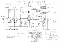
Schaltnetzteil mit Roehren, von Hans-Martin Sauer
Netzteil für Low Power Röhrenverstärker
Compound Tube Contest
Schaltnetzteil mit Roehren, von Hans-Martin Sauer
Netzteil für Low Power Röhrenverstärker
Attachments
Last edited:
i am dreaming of a tube class D amp.....to go along with a tube smps...
In progress...

Something like this?
It a number of options - either an IT up front could run multiple supplies/channels, or simply have one APFC and then run all the supplies/channels off the same 390V DC Link.
Option there is to put a maida style regulator in there for very smooth 390V..
Not finished.. but the idea.. Issue I can see is that a SS diode on the output will start conducting very quickly.. so you'll have a large inrush through the OT..
Last edited:
i saved the page as pdf file, thanks, will try to digest it and go on to build my own, can you share details of the 4.7mh plate choke and the output traffo? and what is the operating frequency? do you have suggestions to provide feedback control from secondary to primary?
Last edited:
In progress...
View attachment 945705
Something like this?
It a number of options - either an IT up front could run multiple supplies/channels, or simply have one APFC and then run all the supplies/channels off the same 390V DC Link.
Option there is to put a maida style regulator in there for very smooth 390V..
Not finished.. but the idea.. Issue I can see is that a SS diode on the output will start conducting very quickly.. so you'll have a large inrush through the OT..
my idea is adaptation of ss circuits replacing the Mosfets with power tubes, driving tubes would be easier since the electrode capacitances are much lower with power tubes...
- Home
- Amplifiers
- Tubes / Valves
- Tube modulated SMPS