Hi All,
Some of you may have been following an interesting thread in which Ralph Karsten of Atma-sphere fame graciously offered the schematic of an early version of the M-60 amplifier, which a number of forum members have built and are happily using. See thread link below -
What tubes for a OTL tube amp?
Thoughts have now turned to a matching pre-amp. As Ralph himself has stated, as the power amp is a differential design, it would make sense to use that advantage with a differential pre-amp. It would, of course, be unreasonable of us to ask Ralph if he would be willing to share a schematic of an early MP-3, (although we have, of course asked, ) but he has explained the concept behind the MP-3 circuitry, and with a little thought and input from forum members we should hopefully be able to put together something very close to the real thing.
Ralph's comments are below -
The circuit is very similar to the M-60 but uses a straight differential amplifier driving the grids of the output tube which is a 6SN7 rather than a power tube. Because its easier to drive no driver tube is needed. We usually run the Circlotron supplies at about 120V at their outputs. A servo is used to detect DC Offset at the output XLRs. One of the grids of the 6SN7 is tied thru a 1M resistor to a simple divider network so that the tube is biased at about -1.7V. The output of the servo ties to the other grid thru another 1M resistor and there is a bit of capacitance at the point where that ties to the divider network or output of the servo, to prevent modulation of the network by actual audio.
This is probably a topic for another thread. But this circuit is arguably as transparent as you'll ever get using tubes, with extreme bandwidth too. The main advantage is that no enormous output coupling cap; instead the Circlotron acts as a buffer so the actual coupling caps can be much smaller. The smaller you make the cap the less inductance and other problems it has so it can be more neutral.
So, the gauntlet has been laid down and the proverbial carrot well and truly dangled.
The problem I personally have is that whilst I can use a soldering iron, and can happily read a schematic, I do not have the design skills to interpret Ralph's comments into a workable design. Hopefully however, there are plenty of forum members who can, and so the plan is to develop the design into a workable solution that can be built by forum members who are interested in this type of circuit topology. If there is sufficient interest, then hopefully a group buy of pcb's could be organised.
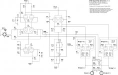
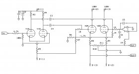
As a starting point, I have added below the circuit diagram for the DIY Audio version of the M-60 that I am currently building, plus a concept schematic of a pre-amp based on Ralph's comments above.
I fully accept that the schematic is almost certainly not workable in its current form, but hopefully this can be developed into a suitable design. Please feel free to comment and adjust as required. One of the great benefits of this hobby for me is that it gives me the opportunity to learn. So happy to co-ordinate reply's and modify the design to suit.
So. . .
V1 is a 12AU7
V2 is a 6SN7
This will only be the line stage at the moment.
Although the MP-3 is a fully differential design, have only spec'd a single ended input, (as most people will probably not be able to make use of a fully balanced input) but this can of course easily be modified by adding the second input into V1B
R5 could be changed for a CCS, although I don't think Ralph uses one.
R6 and R7 are the voltage divider that Ralph mentions for the -1.7V bias voltage on the output tubes.
So thoughts please. Hopefully Ralph will also add in a few comments as we go.
Cheers,
Steve.
Some of you may have been following an interesting thread in which Ralph Karsten of Atma-sphere fame graciously offered the schematic of an early version of the M-60 amplifier, which a number of forum members have built and are happily using. See thread link below -
What tubes for a OTL tube amp?
Thoughts have now turned to a matching pre-amp. As Ralph himself has stated, as the power amp is a differential design, it would make sense to use that advantage with a differential pre-amp. It would, of course, be unreasonable of us to ask Ralph if he would be willing to share a schematic of an early MP-3, (although we have, of course asked,
) but he has explained the concept behind the MP-3 circuitry, and with a little thought and input from forum members we should hopefully be able to put together something very close to the real thing.Ralph's comments are below -
The circuit is very similar to the M-60 but uses a straight differential amplifier driving the grids of the output tube which is a 6SN7 rather than a power tube. Because its easier to drive no driver tube is needed. We usually run the Circlotron supplies at about 120V at their outputs. A servo is used to detect DC Offset at the output XLRs. One of the grids of the 6SN7 is tied thru a 1M resistor to a simple divider network so that the tube is biased at about -1.7V. The output of the servo ties to the other grid thru another 1M resistor and there is a bit of capacitance at the point where that ties to the divider network or output of the servo, to prevent modulation of the network by actual audio.
This is probably a topic for another thread. But this circuit is arguably as transparent as you'll ever get using tubes, with extreme bandwidth too. The main advantage is that no enormous output coupling cap; instead the Circlotron acts as a buffer so the actual coupling caps can be much smaller. The smaller you make the cap the less inductance and other problems it has so it can be more neutral.
So, the gauntlet has been laid down and the proverbial carrot well and truly dangled.
The problem I personally have is that whilst I can use a soldering iron, and can happily read a schematic, I do not have the design skills to interpret Ralph's comments into a workable design. Hopefully however, there are plenty of forum members who can, and so the plan is to develop the design into a workable solution that can be built by forum members who are interested in this type of circuit topology. If there is sufficient interest, then hopefully a group buy of pcb's could be organised.
As a starting point, I have added below the circuit diagram for the DIY Audio version of the M-60 that I am currently building, plus a concept schematic of a pre-amp based on Ralph's comments above.
I fully accept that the schematic is almost certainly not workable in its current form, but hopefully this can be developed into a suitable design. Please feel free to comment and adjust as required. One of the great benefits of this hobby for me is that it gives me the opportunity to learn. So happy to co-ordinate reply's and modify the design to suit.
So. . .
V1 is a 12AU7
V2 is a 6SN7
This will only be the line stage at the moment.
Although the MP-3 is a fully differential design, have only spec'd a single ended input, (as most people will probably not be able to make use of a fully balanced input) but this can of course easily be modified by adding the second input into V1B
R5 could be changed for a CCS, although I don't think Ralph uses one.
R6 and R7 are the voltage divider that Ralph mentions for the -1.7V bias voltage on the output tubes.
So thoughts please. Hopefully Ralph will also add in a few comments as we go.
Cheers,
Steve.
Attachments
Hi Lampie519,
Thanks for your comments.
Yes, I agree that we could use output coupling caps to remove the need for a DC servo on the output, but the MP-3 uses a servo, and of course no output cap is preferable even to the highly regarded (and extremely expensive) V Caps that Ralph offers as an upgrade on his amps where one is used.
I appreciate that there are many options and ideas, and that's one of the great advantages of these forums, we we can debate the pro's and con's, but as far as I am concerned, Ralph is a highly respected designer and manufacturer, so if he uses DC servos instead of coupling caps then that's good enough for me. Of course if anyone wants to have a go at building the amp with the caps then it would be a very simple mod, and we could even produce a pcb with both options if it ever got that far.
Cheers,
Steve.
I understood you wanted to use this as preamp not poweramp. So i don’t understand why you want to use a dc servo here. Please be aware that usually the input load of a next amp is not 8 or 16 Ohm but much higher. A small dc offset to the loudspeakers is of no concern but it is at any input of a gain stage.
Hi Lampie519,
Yes, this is a preamp. I am assuming Ralph uses a DC servo as he feels that sonically this is better than having a coupling cap in the signal path. As I stated in the first post I am not a designer, so unfortunately cannot really comment on the pros and cons of each, but hopefully Ralph may chip in at some stage to explain his reasoning behind this choice.
Cheers,
Steve.
It is not the case here as he IS using coupling caps. These are placed between the first and second stage. Now only for the loudspeaker output he decided not to use any (this is done so in many OTL amps). He then would have needed very big caps (1000uF upwards). So to do it this way is more cost effective. There are no audible benefits at this spot of the amp. If you would like to have less coupling capacitors in the signal path then remove the ones between the first and second stage. Some ground lifting of the second stage is required but no negative bias voltage is needed as well in a preamp.
I understood you wanted to use this as preamp not poweramp. So i don’t understand why you want to use a dc servo here. Please be aware that usually the input load of a next amp is not 8 or 16 Ohm but much higher. A small dc offset to the loudspeakers is of no concern but it is at any input of a gain stage.
DC servo would be required if there are no coupling caps. If there were a DC offset and you were driving a capacitively coupled input stage it is a don’t care. But if you’re driving a *transformer coupled* input stage, which is often the case with balanced inputs, you don’t want any DC - even millivolts.
In a preamp the opamp is not needed as usually some capacitors are used in the signal path to the output connectors. No DC balancing is required then. Only if you would like to have a DC output ( not recommended here) it needs to be implemented.
This preamp design goal was to have a direct-coupled balanced output. The original circuit was in our MP-1 and was the first balanced line preamp offered to home audio. The MP-3 is a single-chassis version of that original design.
The reason for this was to properly support the balanced line standard (a.k.a. AES48) which otherwise has to be done with an output transformer. The Circlotron can behave very much like an output transformer in that the ground connection is only used for shielding.
So a servo is employed to prevent DC Offsets from causing issues with the power amplifier. Since solid state amps can be quite bothered by DC at their inputs, the servo had to prevent DC from being more than a few millivolts. We set up the DC Offset LEDs to light up at about 12mV at the output of the circuit.
The circuit is similar to the M-60 circuit posted but of course is using a 6SN7 as the sole output tube and no need of a driver circuit, just a differential amplifier is all that's needed.
If you use coupling capacitors you can't support AES48 since their use will require a ground return circuit. You also have to support driving fairly low impedances such as 1000 ohms, even though most home audio amplifiers have much higher input impedance.
It IS lifted ...
The XLR plug “proves” this...
So to answer you question.... YES[/QUOTE
Yes you are correct for the amp schematic. I simply thought the posted pre-amp schematic should reflect the amp's input circuit.
I don’t think a transforner of some kind is required to comply to the AES48 standard even if your implementation is a nice one. Coupling caps can still be used and still be within this standard as long as there is a seperate ground and shield. I could be wrong but it would surprise me as most pro equipment nowadays do not use transformers and do not use the MP-3 implementation. Do they all not comply?
Best regards,
Frank
Best regards,
Frank
Just looking at that - the 6SN7 heaters are ok on the cascode as the zenner would keep the voltage low (well 47V + the peak < Uhk) but the cathode hung differential stage (V4) may need elevated heaters?
I'm being cheeky and looking at the front end of that with BH7s driving a PP output stage in LTspice atm. 6SN7 is a little more forgiving on the heater than the mini-me tubes but I think that V4 may need some attention.
I'm being cheeky and looking at the front end of that with BH7s driving a PP output stage in LTspice atm. 6SN7 is a little more forgiving on the heater than the mini-me tubes but I think that V4 may need some attention.
I don’t think a transforner of some kind is required to comply to the AES48 standard even if your implementation is a nice one. Coupling caps can still be used and still be within this standard as long as there is a seperate ground and shield. I could be wrong but it would surprise me as most pro equipment nowadays do not use transformers and do not use the MP-3 implementation. Do they all not comply?
Best regards,
Frank
The bit about a separate ground is what is throwing you off. The problem is you have to support driving a fairly powerful signal to the receiver without referencing ground. Most balanced tube circuits I've seen use dual cathode followers and since that is referencing ground, although it is balanced, its not supporting the standard.
A transformer can make its output signal without referencing ground with ease. Since a Circlotron can be referenced to any voltage potential (such as ground) but does not reference that potential to make its output, it can do it too.
It is true that most balanced tube preamps use some kind of cathode follower (so does mine). So i understand the benefits of this approach now.
Would it be required then if the input impedance of the poweramp is in the range of 100k to 1M Ohm ( as in my case) ? Also as i do not need to comply to any standard (as diyer).
I think in this case there is no extreem low output impedance needed and dc blocking caps could be used as i mentioned earlier to simplify the amp and move the coupling caps one stage making them less audible.
Maybe i have to build it to find out for myself haha.
Thanks for your constructive feedback !
Best regards,
Frank
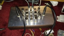
Attachments
1M is an extremely high input impedance- that will cause the amp to be very susceptible to cable capacitance.Would it be required then if the input impedance of the poweramp is in the range of 100k to 1M Ohm ( as in my case) ? Also as i do not need to comply to any standard (as diyer).
I think in this case there is no extreem low output impedance needed and dc blocking caps could be used as i mentioned earlier to simplify the amp and move the coupling caps one stage making them less audible.
Maybe i have to build it to find out for myself haha.
Thanks for your constructive feedback !
Best regards,
Frank
When the ground is ignored ground loops stop being an issue. You also get cable immunity because the signal return isn't going thru the shield. The low impedance aspect helps swamp cable capacitance. This all adds up to allowing you to run inexpensive cables some fairly long distances without degradation.
But all the aspects have to be observed.
I agree that all the aspects need to be observed and that all little bits help improving the sound.
As for ground returns in balanced cables i think it is a non issue (as long as the current is indeed symmetrical) as they will cancel each other out at the sink device. I know with tubes only in SPICE simulations we see perfect symmetry as in the real world it would be only temporary or with huge amounts of feedback so indeed when done without any ground return we also do not worry about this.
As for ground returns in balanced cables i think it is a non issue (as long as the current is indeed symmetrical) as they will cancel each other out at the sink device. I know with tubes only in SPICE simulations we see perfect symmetry as in the real world it would be only temporary or with huge amounts of feedback so indeed when done without any ground return we also do not worry about this.
The problem with a signal return in the shield is first the balance between the alternate signals has to be perfect and won't be if ground is referenced. It will always be perfect if the ground is ignored.
The second problem is using the ground opens you up to ground loops and while you may not always hear a hum, a ground loop can increase distortion.
The second problem is using the ground opens you up to ground loops and while you may not always hear a hum, a ground loop can increase distortion.
- Home
- Amplifiers
- Tubes / Valves
- Differential preamp based on the Atma-sphere MP-3