I've been continuing to look at the M60 front end and I like it.
So there's a CCS running into a differential cascode that the supplies a driver stage to drive the parallel 6as7s.
Ignoring the CCS - I wanted to discuss the topology, voltage and harmonic cancellation opportunities.
The big 300V+ gives the 6sn7 space to breath and have a decent plate load to get the best out of them. I assume each of the 6sn7s have identical voltage across the tube within the cascode.
The zenner I thought was masterful, and allows very easy configuration of the voltages. I also like the B+/B- use in the front stages to provide power ripple cancellation.
The driver stage is sat way up - I assume (I've not modelled the 6sn7 version) that the voltage across these matches the same voltage as the previous input cascode tubes?
I can see the driver means we're not overloading tasks onto the cascode and it provides an appropriate load seen through the capacitor.. but I think there's a missing opportunity.
If we put the signal+harmonics through the driver stage and take the plate, we're essentially providing the opportunity to cancel the harmonics?
My limited experience but I've not see a cathode attached driver like this - does the same harmonic cancellation effect occur?
Lastly-- cathode injected even harmonics can (supposedly) cause odd harmonics. So with a 6SN7 based CCS does this cause additional odd harmonic production?
Last edited:
There's actually a different thread that is focused more on this circuit. But thanks for your comments.The big 300V+ gives the 6sn7 space to breath and have a decent plate load to get the best out of them. I assume each of the 6sn7s have identical voltage across the tube within the cascode.
The zenner I thought was masterful, and allows very easy configuration of the voltages. I also like the B+/B- use in the front stages to provide power ripple cancellation.
The driver stage is sat way up - I assume (I've not modelled the 6sn7 version) that the voltage across these matches the same voltage as the previous input cascode tubes?
I can see the driver means we're not overloading tasks onto the cascode and it provides an appropriate load seen through the capacitor.. but I think there's a missing opportunity.
If we put the signal+harmonics through the driver stage and take the plate, we're essentially providing the opportunity to cancel the harmonics?
My limited experience but I've not see a cathode attached driver like this - does the same harmonic cancellation effect occur?
Lastly-- cathode injected even harmonics can (supposedly) cause odd harmonics. So with a 6SN7 based CCS does this cause additional odd harmonic production?
You get distortion cancellation at each stage throughout the circuit. The driver circuit is direct coupled to the output section since the grids of the power tubes have a substantial capacitance, and this prevents a variety of issues that would be associated with using coupling caps between the driver and output tubes. One advantage is the driver easily drives the power tubes into grid current, allowing for class A2 operation.
The CCS improves differential effect and so reduces distortion while also increasing the gain that you would get if a simple resistor were used. The B- is helpful to give the CCS tube nice operating points.
The MP-3 line stage circuit operates in a similar manner but since the 6SN7 has insignificant grid capacitance the driver tube isn't needed. You don't need the gain either so a simple differential amplifier is used. It does benefit from a CCS circuit and the one employed by the M-60 works quite well. But we run the B+ and B- at a regulated 250V instead of 300V. So we've been using a solid state CCS instead.
An opposing power supply of equal potential. The two power supplies connected in this manner with the pair of output devices is a circuit known as a Circlotron.In the other schematic, the out+ is connected to B-. So what is preventing current flow?
Hi All,
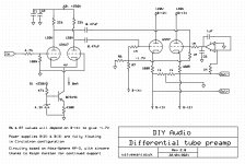
Good to see some interesting discussion on the merits of the circuitry. As we have not yet had any input and suggestions on the validity of proposed schematic I posted at the start of the thread, (or any component values if all is OK) have decided to have a go myself using my (very) limited knowledge of circuit design.
So new schematic attached with most of the component values now in place.
Changes are as follows -
Have implemented a simple CCS on the tail of the differential input. Using an NPN transistor should (I believe) allow us to remove the -ve supply rail on the input, although this does now mean we will need to generate some -ve voltage for the -1.7V bias on the 6SN7's
The 12AU7 has been set up with a quiescent current of 4mA per triode section
Have made a guess at the resistor values at the output & around the cathodes of the 6SN7. Have no idea if these are realistic.
Have left the dc servo in place as I am hoping we can end up with something in keeping with the basic design concept of the MP-3. I appreciate Lampie519's comments that a capacitor would be a simpler solution, but we've already got one in the signal path and would like to remove the need for a 2nd. Ralph has mentioned that we need some capacitance on the output of the servo, but not sure what value that may be.
Please feel free to comment and amend as required.
Cheers,
Steve.
Attachments

We use 49.9K plate resistors for the 12AU7. The servo will need an identical cap as used in the feedback.
A two-stage CCS is more effective! Single-stage CCS circuits leave a lot of performance on the table. The zener bias resistor can go to ground. If you run a - 12V filament supply that is grounded, you can run the CCS off of it. In practice we run the CCS off of a minus 250V supply- essentially doing everything we can get ideal operation out of the CCS.
The cap at the output of the servo won't work right. If the opamp drives the same value of resistor as R6 then you can make that cap work. I would run the bias network to the minus side of the filament supply if you go that route.
I would consider increasing the values of the 1K resistors that reference the Circlotron to ground, maybe to 10K or higher. Also, consider tying them together to a resistor of perhaps 100ohms or so to ground, so there is a bit of common mode action.
Anyone tried a pentode instead of a triode in the second stage (cross coupled screen grids) ?
I think the output impedance could drop substantially plus it could be more linear. Just a thought.
My preamp is 4x mono as my dac is delivering a dual mono output ( floating grounds). The power amp has a phase inverter implemented so none is needed in my preamp. All imperfect ballanced signals will be dealt with in my power amp (that was the idea). It works very well in practice but my guess is that it is not according to “the book”
Any feedback is appreciated as always ...
Best regards,
Frank
Last edited:
I believe the input resistors after the 150k pot's are 1M, 1M on both pin 2 and 7 on the 12AU7. And a gain trim pot between 3&8 with series resistors to B-
Parallel resistor to the cap needed on the servo feedback.
Maybe adding series resistors to the coupling caps.
Parallel resistor to the cap needed on the servo feedback.
Maybe adding series resistors to the coupling caps.
Anyone tried a pentode instead of a triode in the second stage (cross coupled screen grids) ?
I think the output impedance could drop substantially plus it could be more linear. Just a thought.
My preamp is 4x mono as my dac is delivering a dual mono output ( floating grounds). The power amp has a phase inverter implemented so none is needed in my preamp. All imperfect ballanced signals will be dealt with in my power amp (that was the idea). It works very well in practice but my guess is that it is not according to “the book”
Any feedback is appreciated as always ...
Best regards,
Frank
Its hard to imagine a pentode having a lower output impedance and greater linearity than a triode but I'm sure there's a first time- a lot would depend on what triode (in this case a 6SN7) and what pentode...
If you deliver a balanced signal to a power amp that is otherwise balanced, unless that amp has a very high Common Mode Rejection ratio then it will have lower distortion when driven by a balanced source. So its good practice to make sure the line section has a reasonable CMRR as well!
I believe the input resistors after the 150k pot's are 1M, 1M on both pin 2 and 7 on the 12AU7. And a gain trim pot between 3&8 with series resistors to B-
Parallel resistor to the cap needed on the servo feedback.
Maybe adding series resistors to the coupling caps.
We no longer use the degeneration-style Gain Trim controls having opted for shunt controls instead. They have no noise when used and of course have full range control.
You don't need a parallel resistor to the cap in the feedback loop. But you very much need an identical cap to ground off of the opamp's other input!
I'm glad you mentioned the grid resistors of the 12AU7; I missed that one grid was simply being grounded in the schematic just above. It should instead be used as an input in case of a balanced source. The volume control should of course have 4 decks- one deck for each phase of each channel. The 1M resistors are there just in case; the volume control is essentially the grid resistor. I also forgot to mention that grid stop resistors should be used at the grids of all the tubes in the circuit.
Last edited:
Thanks, and yes balanced is what we (I) want all the way through.
I am admittedly referencing some details on how the design looked more than 20 years ago - and I'm not deeply into the circuit design. So this is really great for understanding the choices and pitfalls.
For sure the cap is needed on the DC servo, also expect that some adjustments might be needed to the value to ensure an optimal response.
I did expect to get away with lower input impedance and use more readily available 50k or 100k potentiometers
Last edited:
The circuit is essentially a follower of some kind and pentodes make great followers. Lower output impedance plus more linear (nothing new here). So it could be worth trying at least.
Not sure if balanced is the way to go but in some cases it just asks for it (like in my case as electrostatic loudspeakers are by nature balanced). So are my power amps and the source etc. Naturally all speakers can be called balanced but do not need to be driven that way. There are disadvantages of balanced amps as well (as stated earlier).
So only if done right and if you do not care too much of unbalance in case the tubes age then you can go for it.
Best regards,
Frank
For sure the cap is needed on the DC servo, also expect that some adjustments might be needed to the value to ensure an optimal response.
I did expect to get away with lower input impedance and use more readily available 50k or 100k potentiometers
100K seems to work out well without serious Miller Effect issues with the 12AU7. A lower value works too but keep in mind that we have to assume that some sources might have a higher output impedance. So you have to balanced that against Miller Effect issues- and in this case we have a fair bit of leeway. So 100K is easy to find in good quality and works well.
For many years we've used a custom-built 4 deck switch for the master volume control, simply because the line state is arguably one of the most transparent tube line stages made at any cost (owing to the direct-coupled output).
I probably should point out that we obtained two different patents on how this is done, so it should be understood that this information is being provided by me for personal use only!
The circuit is essentially a follower of some kind and pentodes make great followers. Lower output impedance plus more linear (nothing new here). So it could be worth trying at least.
Not sure if balanced is the way to go but in some cases it just asks for it (like in my case as electrostatic loudspeakers are by nature balanced). So are my power amps and the source etc. Naturally all speakers can be called balanced but do not need to be driven that way. There are disadvantages of balanced amps as well (as stated earlier).
So only if done right and if you do not care too much of unbalance in case the tubes age then you can go for it.
Best regards,
Frank
Triodes make good followers too. They trade off less voltage loss across the circuit for lower output impedance and greater linearity.
I don't know what the disadvantage of a balanced amp might be other than more parts. The actual signal path can be simpler, as seen in our M-60 which has only a single stage of voltage gain.
In terms of distortion the advantage is significant! Even orders are cancelled at each stage throughout the circuit, meaning that distortion is not compounded as much from stage to stage.
That means that the most significant distortion component will be the 3rd harmonic, which is treated by the ear in exactly the same way as it treats the 2nd, which is to say it insensitive to it, and the tonality assigned to it by the ear causes 'warmth' and 'bloom' as audiophiles often describe the 2nd harmonic. But it will be generated at a significantly lower level than circuits that make the 2nd order, so there will be less coloration.
Because even orders are cancelled, mathematically we have a different kind of non-linearity as opposed to a single-ended circuit. The way a single-ended circuit generates distortion is described mathematically as a 'quadratic non-linearity'. When the circuit is fully balanced and differential, with a 3rd harmonic as its main distortion product, it has what is called a 'cubic non-linearity'.
This is actually important; with a cubic non-linearity as the order of the harmonic is increased, its amplitude falls off at a greater rate than seen with a quadratic non-linearity. Since there is less higher ordered harmonic content as a result, a fully balanced circuit will sound smoother to the ear because the ear assigns brightness and harshness to the higher orders and is keenly sensitive to their presence (it uses them to sense sound pressure)!
It will also be more detailed simply because there is less distortion.
This all assumes there is no feedback which complicates matters and is a separate conversation.
I am not against balanced amps ( i am a user myself) but as mentioned earlier, the symmetry is not ensured using tubes without feedback. This is not a big issue as no circuit is without some compromises. Sure you can argue about the harmonics in a SPICE simulation but in real life you will have unbalance and the theory does not add up anymore. Then making a choice between balanced or unbalanced becomes less obvious.
This also can be seen in pro equipment as the mic amps are unbalanced and master amps are balanced. ( i use a console with V77 and V77b preamps for recording life music).
Best regards,
Frank
This also can be seen in pro equipment as the mic amps are unbalanced and master amps are balanced. ( i use a console with V77 and V77b preamps for recording life music).
Best regards,
Frank
Sure you can argue about the harmonics in a SPICE simulation but in real life you will have unbalance and the theory does not add up anymore. Then making a choice between balanced or unbalanced becomes less obvious.
This also can be seen in pro equipment as the mic amps are unbalanced and master amps are balanced. ( i use a console with V77 and V77b preamps for recording life music).
Best regards,
Frank
I'm making this argument for real life- it hadn't occurred to refer to a SPICE simulation; we simply see it in the measurements. You are correct that some imbalanced will occur, but you can see from the measurements that the 3rd dominates, so this holds out in a real-world application. We've been making amps of this type for a very long time; our first fully differential balanced amps date from about 1985.
This is really all about coloration but when you are talking about recording there are a lot more variables as you well know. All of our mic preamps are single-ended with transformer inputs as well. They provide a nice coloration despite how neutral they seem to sound. Put another way they don't sound colored, until:
We have built some mic preamps based on the MP-3 circuit of this thread by simply dispensing with the EQ circuit in the phono section and reducing its overall gain. That approach is even more neutral...
Hello Ralph, do you really think that single-ended preamp will be less detailed as opposed to balanced one in terms of micro level music details ? Fundamental problem of balanced topology lies at the inability to sum up the signal perfectly at the end and this is the result of inevitable (because of tubes, details non-matching at operating points) disbalance of the balanced "shoulders" of topology.
Hi All
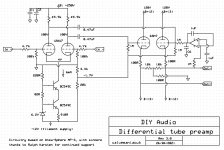
Schematic updated in line with the discussions above.-
Anode resistors on input tube changed to 49.9k
Cascoded CCS added, using -12V supply from filaments as suggested by Ralph.
Resistor values on output updated in line with Ralph's comments.
DC servo still needs some work, but I am now at the limit of my capabilities on circuit design, so need some help please. If some-one can sketch out a working solution, I'll happily add it into the main schematic.
Probably not too far away from a workable solution now. Please remember this design will need multiple power supplies. At least 1 for the input tube(s), 4 for the output stage and 1 for the filaments, assuming they can all be fed from the same one. Please feel free to suggest the best way to implement these.
Cheers,
Steve.
Attachments
Hello Ralph, do you really think that single-ended preamp will be less detailed as opposed to balanced one in terms of micro level music details ? Fundamental problem of balanced topology lies at the inability to sum up the signal perfectly at the end and this is the result of inevitable (because of tubes, details non-matching at operating points) disbalance of the balanced "shoulders" of topology.
I suspect you're working with a misconception. If the circuit is fully differential as opposed to merely balanced, what you are describing isn't a serious issue. The output of the Circlotron floats at ground potential but does not reference it. Its '+' output is with respect to its '-' output so its like an output transformer in that regard. It won't matter if the drive to the Circlotron isn't perfectly symmetrical- the outputs will remain equal and opposite.
You might consider a zener to ground in the CCS rather than using a resistor. In this way the base of the top transistor will be kept at a constant voltage. You may need protection diodes between the base and emitter of each transistor. The coupling caps can be 0.047uf and will work quite well- I would not use more than 0.1uf.Hi All
Schematic updated in line with the discussions above.-
Anode resistors on input tube changed to 49.9k
Cascoded CCS added, using -12V supply from filaments as suggested by Ralph.
Resistor values on output updated in line with Ralph's comments.
DC servo still needs some work, but I am now at the limit of my capabilities on circuit design, so need some help please. If some-one can sketch out a working solution, I'll happily add it into the main schematic.
Probably not too far away from a workable solution now. Please remember this design will need multiple power supplies. At least 1 for the input tube(s), 4 for the output stage and 1 for the filaments, assuming they can all be fed from the same one. Please feel free to suggest the best way to implement these.
Cheers,
Steve.
DC Servo question
I'm currently trying to understand the DC servo bit on the output stage, and as I am totally out of my depth here, please accept my apologies if I am asking a dumb question.
Ralph has already mentioned that the output tubes are biased at -1.7V. So, do we need to set up a bias voltage for both triode sections in the 6SN7, or do we bias one, and then let the servo sort out the other one. The bit I'm struggling to understand is what happens if we bias both sections, as the DC servo is then fighting with one of them to alter the bias to correct the DC offset.
Cheers,
Steve.
Hi All,
Just been re-reading through Ralph's posts in M-60 thread, and have now answered my own question.
As I mentioned in an earlier post, one of the benefits for me is learning and understanding these circuits a little better. As a result, Ralph's explanations and comments are now making much more sense to me than they were 3 - 4 weeks ago.
Cheers,
Steve.
- Home
- Amplifiers
- Tubes / Valves
- Differential preamp based on the Atma-sphere MP-3