Hi,
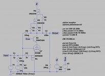
I want to share the results I've obtained simulating an hybrid cascoded driver with local feedback à la CED/UNSET. ...it's like retriodize a cascoded triode.
The idea has been inspired by Tubelab's CED and UNSET and from SpreadSpectrum's CORONA amp (https://www.diyaudio.com/forums/tub...a-low-distortion-a2-dht-se-amp-prototype.html)
1.4Vpp input give 140 Vpp output, and a THD of 0.047%:
I've obtained ppm-like distortions with higher local-feedback ratios, but everything still need to be optimized.
I want to share the results I've obtained simulating an hybrid cascoded driver with local feedback à la CED/UNSET. ...it's like retriodize a cascoded triode.
The idea has been inspired by Tubelab's CED and UNSET and from SpreadSpectrum's CORONA amp (https://www.diyaudio.com/forums/tub...a-low-distortion-a2-dht-se-amp-prototype.html)
1.4Vpp input give 140 Vpp output, and a THD of 0.047%:
Code:
Harmonic	Frequency	 Fourier 	Normalized	 Phase  	Normalized
 Number 	  [Hz]   	Component	 Component	[degree]	Phase [deg]
    1   	1.000e+03	6.706e+01	1.000e+00	   -0.76°	    0.00°
    2   	2.000e+03	3.151e-02	4.699e-04	   97.42°	   98.18°
    3   	3.000e+03	8.770e-04	1.308e-05	   98.39°	   99.15°
    4   	4.000e+03	3.044e-04	4.539e-06	  177.17°	  177.94°
    5   	5.000e+03	1.170e-04	1.745e-06	 -142.30°	 -141.53°
    6   	6.000e+03	3.823e-05	5.700e-07	 -172.56°	 -171.80°
    7   	7.000e+03	5.862e-05	8.741e-07	  165.29°	  166.05°
    8   	8.000e+03	5.931e-05	8.844e-07	  178.26°	  179.02°
    9   	9.000e+03	4.730e-05	7.053e-07	 -175.67°	 -174.91°
Total Harmonic Distortion: 0.047008%(0.047001%)
I've obtained ppm-like distortions with higher local-feedback ratios, but everything still need to be optimized.
Attachments
'cause it makes a nice orageish colour when the light is off, and I still haven't found a led with the same nuance.
The idea is to have a driver where you can set the second harmonic distortion with a simple pot that changes the load it sees, depending on what you are listening to: load it with 10k and you'll get around 1.3% second harmonic, whilst all others harmonics stay at least 2-3 order of magnitude lower. Load it with 1 MOhm and you'll get almost no distortion at all.
It can become a control of the amp to adapt it to the genre you are listening to.
Last edited:
Thank you v4lve lover!
I've found the following thread: cascode tubes and the datasheet: https://frank.pocnet.net/sheets/009/e/ECC2000.pdf but not a LTSpice model for it yet.
I will search this evening.
I've found the following thread: cascode tubes and the datasheet: https://frank.pocnet.net/sheets/009/e/ECC2000.pdf but not a LTSpice model for it yet.
I will search this evening.
Remind me again about why there's a vacuum valve in there at all?
YOS,
Chris
very good consideration!
🙂
Walter
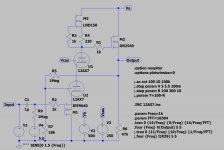
Done some mods during the coffee break with a cascoded 12AX7 and a buffered output: 1.5Vp input, 170Vpp output with 0,009% THD
Code:
Harmonic	Frequency	 Fourier 	Normalized	 Phase  	Normalized
 Number 	  [Hz]   	Component	 Component	[degree]	Phase [deg]
    1   	1.000e+03	8.431e+01	1.000e+00	   -0.30°	    0.00°
    2   	2.000e+03	7.515e-03	8.914e-05	   38.14°	   38.44°
    3   	3.000e+03	1.203e-03	1.427e-05	   55.82°	   56.12°
    4   	4.000e+03	5.053e-04	5.994e-06	  108.06°	  108.36°
    5   	5.000e+03	1.515e-05	1.797e-07	  -56.80°	  -56.50°
    6   	6.000e+03	1.278e-04	1.516e-06	   95.24°	   95.54°
    7   	7.000e+03	3.865e-05	4.585e-07	 -172.80°	 -172.50°
    8   	8.000e+03	3.813e-05	4.522e-07	  100.06°	  100.36°
    9   	9.000e+03	3.343e-05	3.965e-07	 -171.66°	 -171.36°
Total Harmonic Distortion: 0.009049%(0.009010%)
Attachments
ECC88 max anode dissipation about 1.8W.
In this sketch it's about 4W!
Thanks for the head-up euro21. I've checked it with the 12AX7 version and I'm within limits at 400 mW per triode.
Thanks rufus74pz, each triode belongs to a different envelope in a stereo amp.
One 12ax7 belongs to the bottom, one to the top. Bottom is elevated by 40 V circa like power tubes, top is referred to 3/4 of B+ through a voltage divider (like 330k and 1M).
One 12ax7 belongs to the bottom, one to the top. Bottom is elevated by 40 V circa like power tubes, top is referred to 3/4 of B+ through a voltage divider (like 330k and 1M).
Last edited:
I like it. I did some experiments a while back with CCS-loaded pentodes with local plate-to-grid feedback here: Idea for driver for CF output stage
It was parallel-applied rather than series-applied like you are doing but I used the p-channel fet follower to drive the feedback network and give high input impedance. Distortion was quite low and bandwidth high, even at ridiculous output levels.
Doing a cascode instead of a pentode is neat, and I'm sure this would perform really well in a real circuit as well.
Thank you very much SpreadSpectrum!
I will read that thread this evening, I'm very interested.
I will also try to dc couple a mosfet concertina to that gain stage, to adapt it to PP amps too.
I attach here the jpg of the schematic with cascoded 12AX7.
I will read that thread this evening, I'm very interested.
I will also try to dc couple a mosfet concertina to that gain stage, to adapt it to PP amps too.
I attach here the jpg of the schematic with cascoded 12AX7.
Attachments
Thanks rufus74pz, each triode belongs to a different envelope in a stereo amp.
One 12ax7 belongs to the bottom, one to the top. Bottom is elevated by 40 V circa like power tubes, top is referred to 3/4 of B+ through a voltage divider (like 330k and 1M).
Yesterday evening I was rethinking about it. It can be done easier with one single heater supply referenced at +120V: Vhk will be +120V on the bottom tube and -130V on the top tube, both will swing very few volts, so it will be well within the ±200V shown on the datasheet.
You might also want to check the distortion at higher frequencies. Above 10kHz THD is not particularly low.
Thank you bohrok2610.
Is there any capacitance playing against THD at higher frequencies?
I did a frequency plot and it seemed very linear, but not a simulation at 10 kHz.
PS:
Is it possible to directly drive the primary of a transformer with a stronger buffer?
The buffer actually swings from 320 to 500V. I can split the PSU in two: 0-300V 50mA and 300-500V 2A, then load the buffer with the primary of an output transformer?
I'm not sure how accurate the simulation is in regards to distortion. It seems to be quite dependent on the models. Various 12AX7 models give different results. If you change the upper triode to 12AU7 the distortion above 10kHz is significantly lower. However not so at 1kHz.
It would be needed someone more experienced than me in analysing simulations.
And of course try it in real life.
And of course try it in real life.
You might also want to check the distortion at higher frequencies. Above 10kHz THD is not particularly low.
What numbers do you get? I've just simulated and I get 0,07% at 10 kHz.
It seems very good for 170 Vpp.
Code:
Harmonic	Frequency	 Fourier 	Normalized	 Phase  	Normalized
 Number 	  [Hz]   	Component	 Component	[degree]	Phase [deg]
    1   	1.000e+04	8.425e+01	1.000e+00	   -3.10°	    0.00°
    2   	2.000e+04	6.219e-02	7.382e-04	  -30.11°	  -27.00°
    3   	3.000e+04	9.481e-03	1.125e-04	   76.41°	   79.52°
    4   	4.000e+04	1.711e-03	2.031e-05	  149.23°	  152.33°
    5   	5.000e+04	1.273e-04	1.511e-06	 -117.74°	 -114.64°
    6   	6.000e+04	1.795e-04	2.130e-06	  130.76°	  133.86°
    7   	7.000e+04	6.099e-05	7.239e-07	 -141.16°	 -138.06°
    8   	8.000e+04	7.139e-05	8.474e-07	  139.26°	  142.36°
    9   	9.000e+04	6.146e-05	7.295e-07	 -134.41°	 -131.31°
Total Harmonic Distortion: 0.074698%(0.074694%)I probably have different models than you. I get 0,08%@10kHz, 0,14%@15kHz and 0,21%@20kHz. If the upper triode is 12AU7 I get 0,04%@10kHz, 0,02%@15kHz and
0,09%@20kHz. But I would not put much weight on these simulated distortion numbers. Better to build and test.
0,09%@20kHz. But I would not put much weight on these simulated distortion numbers. Better to build and test.
- Home
- Amplifiers
- Tubes / Valves
- CED/UNSET/CORONA-like ECC88 hybrid cascoded driver