I am considering an E55L parafeed spud amplifier later this year. I've been doing this tube DIY thing for a little over a year now, want to see if I am overlooking anything and get some feedback.
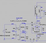
Here is the draft schematic and then some commentary. Note that some part values are stand-ins.

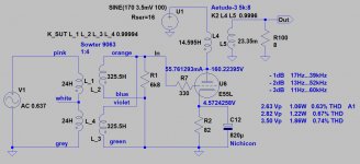
Rather than a plate choke, I would use a cascode CCS load on the E55L. I have a spare Sowter 325VAC 161mA mains transformer with the appropriate voltage to cover the full peak-to-peak E55L plate swing and headroom of the CCS.
I would like to use a 1:2 SUT on the input to reach full output of the E55L with a 2Vrms input.
My mains transformer has three 6.3VAC secondaries. I was thinking of using a voltage doubler on one and going fixed bias since the E55L will only need around -7V on the grid.
The other two 6.3VAC secondaries would be used for the E55L heaters and a tube rectifier.
For the power supply, had thought to use 5V4G or GZ37 for soft start. The Vdrop of the rectifier will help chop off some excess voltage and spare the CCS some heat. Given the PSRR of the CCS, a simple passive CLC supply could be used.
For output transformers, I have swapped emails with Jack and Electra-Print a few times, would like to try his stuff out. I had thought to order a pair of multi-tap 2.5K parafeed transformers with 8, 32, 120, and 300ohm secondaries. This amplifier could do around 2W into 8ohms, so good for a flea-watt speaker setup and gobs of power for headphones.
Thanks for your input
Here is the draft schematic and then some commentary. Note that some part values are stand-ins.
Rather than a plate choke, I would use a cascode CCS load on the E55L. I have a spare Sowter 325VAC 161mA mains transformer with the appropriate voltage to cover the full peak-to-peak E55L plate swing and headroom of the CCS.
I would like to use a 1:2 SUT on the input to reach full output of the E55L with a 2Vrms input.
My mains transformer has three 6.3VAC secondaries. I was thinking of using a voltage doubler on one and going fixed bias since the E55L will only need around -7V on the grid.
The other two 6.3VAC secondaries would be used for the E55L heaters and a tube rectifier.
For the power supply, had thought to use 5V4G or GZ37 for soft start. The Vdrop of the rectifier will help chop off some excess voltage and spare the CCS some heat. Given the PSRR of the CCS, a simple passive CLC supply could be used.
For output transformers, I have swapped emails with Jack and Electra-Print a few times, would like to try his stuff out. I had thought to order a pair of multi-tap 2.5K parafeed transformers with 8, 32, 120, and 300ohm secondaries. This amplifier could do around 2W into 8ohms, so good for a flea-watt speaker setup and gobs of power for headphones.
Thanks for your input
Last edited:
I can highly recommend the Russian magnoval sockets as well.
I prefer solid state rectification, 330VAC is just within reach of some of the common relais like the finder 40.52 series. So you could use a 555 and a relay to delay the application of B+ untill the E55L has warmed up. Not that tube or solid state really matters once you put several meg in series with the circuit (speaking of that cascode CCS impedance)
I prefer solid state rectification, 330VAC is just within reach of some of the common relais like the finder 40.52 series. So you could use a 555 and a relay to delay the application of B+ untill the E55L has warmed up. Not that tube or solid state really matters once you put several meg in series with the circuit (speaking of that cascode CCS impedance)
Yes, exactly my thought, with the CCS in place, the power supply becomes very flexible. I will consider the relay approach, I do like the rectifier to drop some excess B+ voltage to spare the CCS, but of course there are other ways around it. There is the rectifier aesthetic appeal you have read my mind, I have some ceramic Russian magnoval sockets on the way! Thanks for your input.
you have read my mind, I have some ceramic Russian magnoval sockets on the way! Thanks for your input.Hey adamus - no bypassed resistor or string of diodes, I was thinking grid bias, negative bias supply generated from a 6.3VAC winding with a voltage doubler
As for the top FET, the 01 is a stand-in since I do not have a LTSpice model for the 08. But the top FET WOULD likely be the IXTP08N100D2, the bottom either DN2540 or IXTP08N50D2. Unfortunately, the DN2540 is backordered for quite a while, think I might have a few left...
As for the top FET, the 01 is a stand-in since I do not have a LTSpice model for the 08. But the top FET WOULD likely be the IXTP08N100D2, the bottom either DN2540 or IXTP08N50D2. Unfortunately, the DN2540 is backordered for quite a while, think I might have a few left...
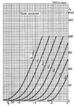
I am afraid this is a very optimistic approach.I would like to use a 1:2 SUT on the input to reach full output of the E55L with a 2Vrms input.
I'm not sure that 1:2 SUT "enough" for 2V RMS (2.82V peek) input.
I tried my SUT as 1:2 (see attachment), but the final layout will be as 1:4.
Little lower HF bandwidth, but after all, the overall limiting factor is the OPT.
I’m beyond the design phase, only the mechanical work is back ... I hate it. :-(
Attachments
"I thought you never use cathode bias!"
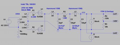
It's a minimal version, only few parts.
I have "small" -2W, and only 2kg weight- 5k:4-8 Monolith transformers, so for this purpose it's right.
+40V is for heater lifting.
If you remains below A1, the 1:2 may be enough, but the desired power will be very reduced.
It's a minimal version, only few parts.
I have "small" -2W, and only 2kg weight- 5k:4-8 Monolith transformers, so for this purpose it's right.
+40V is for heater lifting.
If you remains below A1, the 1:2 may be enough, but the desired power will be very reduced.
Last edited:
cathode bias is superior to some other biasing forms because it is less susceptible to thermal runaway.
Some of the frame grids like the E55L have G1 very close to the cathode, they are insanely built tubes.. And some of the last ever made, the product.. the swan song of tube engineering.
However the flipside of having these frame grid tubes with grids that are wound thinner than the human hair and insanely close to the cathode. Is grid current. I realized this rightaway when i saw your 470K grid resistor in the first post. But i didn't wanna come off like a wise-***. Plenty of that going on here, and im not immume to that myself. Catch me on a bad day, or take a dump on something i really put some thought in, and your in for an intellectual ******* contest to satisfy my ego. But at least im honest about that.
Some ideas you can try: You can try some Sillicon carbide diodes in the cathode lead.. but this means the circuit becomes slightly more suceptible to tube aging.. So if you figured -7V is the sweet spot. Id say use 4 Sic diodes with a resistor in series for the cathode, this provides some local feedback(cathode regeneration)
There is not really a point in bypassing those diodes, cause they have a really low AC impedance.
Some of the frame grids like the E55L have G1 very close to the cathode, they are insanely built tubes.. And some of the last ever made, the product.. the swan song of tube engineering.
However the flipside of having these frame grid tubes with grids that are wound thinner than the human hair and insanely close to the cathode. Is grid current. I realized this rightaway when i saw your 470K grid resistor in the first post. But i didn't wanna come off like a wise-***. Plenty of that going on here, and im not immume to that myself. Catch me on a bad day, or take a dump on something i really put some thought in, and your in for an intellectual ******* contest to satisfy my ego.
But at least im honest about that.Some ideas you can try: You can try some Sillicon carbide diodes in the cathode lead.. but this means the circuit becomes slightly more suceptible to tube aging.. So if you figured -7V is the sweet spot. Id say use 4 Sic diodes with a resistor in series for the cathode, this provides some local feedback(cathode regeneration)
There is not really a point in bypassing those diodes, cause they have a really low AC impedance.
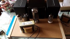
I built just such an amp, and it sounds fantastic. Real clean and simple.
However I have encountered reliability issues with these very expensive valves with quite a few simply flaming out after only a year or so of light use. As such I caution you about building this as a daily driver.
Shoog
However I have encountered reliability issues with these very expensive valves with quite a few simply flaming out after only a year or so of light use. As such I caution you about building this as a daily driver.
Shoog
"I thought you never use cathode bias!"
It's a minimal version, only few parts.
I have "small" -2W, and only 2kg weight- 5k:4-8 Monolith transformers, so for this purpose it's right.
+40V is for heater lifting.
If you remains below A1, the 1:2 may be enough, but the desired power will be very reduced.
I'll give it some thought. Perhaps cathode bias is the simpler approach. In parafeed configuration with the OPT primary returned to the cathode, audibility of the bypass capacitor should be reduced. Let me see on 1:4 SUT. I had planned to use a 2.5K OPT. I had measured E55L on my curve tracer, plate resistance is around 600ohm, true to the datasheet.

cathode bias is superior to some other biasing forms because it is less susceptible to thermal runaway.
Some of the frame grids like the E55L have G1 very close to the cathode, they are insanely built tubes.. And some of the last ever made, the product.. the swan song of tube engineering.
However the flipside of having these frame grid tubes with grids that are wound thinner than the human hair and insanely close to the cathode. Is grid current. I realized this rightaway when i saw your 470K grid resistor in the first post. But i didn't wanna come off like a wise-***. Plenty of that going on here, and im not immume to that myself. Catch me on a bad day, or take a dump on something i really put some thought in, and your in for an intellectual ******* contest to satisfy my ego.
Some ideas you can try: You can try some Sillicon carbide diodes in the cathode lead.. but this means the circuit becomes slightly more suceptible to tube aging.. So if you figured -7V is the sweet spot. Id say use 4 Sic diodes with a resistor in series for the cathode, this provides some local feedback(cathode regeneration)
There is not really a point in bypassing those diodes, cause they have a really low AC impedance.
I see a lot of mean-spirited arguments on this forum, I think it isn't necessary, but the ego battles continue. Lucky for me, I am no engineer and new to the hobby, so I have no ego to defend
most are more knowledgeable than me.So you think grid bias is not practical then. If it were possible of course there would be protection with a fused cathode. I have experimented with SiC diodes in a filament bias configuration, but not as cathode bias. Trying it as well as traditional cathode bias with a film bypass capacitor are worth considering. I am hoping to avoid a prototype, a cathode bias scheme would be more reliable in that regard.
I built just such an amp, and it sounds fantastic. Real clean and simple.
However I have encountered reliability issues with these very expensive valves with quite a few simply flaming out after only a year or so of light use. As such I caution you about building this as a daily driver.
Shoog
Thanks, Shoog, I came across your schematic some time ago, very nice. For me this would not be a daily driver amp, but thank you for the warning. I am not sure how the prices have fluctuated, but I recently purchased a matched sextet of American-made Amperex 8233 for around 70 Euro, pretty good deal if you ask me
I thought for some time your avatar was some sort of catfish...I now see it is a doggo LOL.
Last edited:
I think everyone is getting a bit stirr crazy because they are waiting for tubes that are delayed in the mail
Grid bias is a no go for me, unless you are fine with like 10K input impedance.. which is reflected to 40K for the tube grid. But that may cause trouble if you want to build another box with glass on it to drive it down the road.
If you only need 7V cathode bias is the way to go hands down for reliability and simplicity.
Also, from what ive read. just about everything in the Amperex plant was imported from Holland..
Last edited:
- Status
- This old topic is closed. If you want to reopen this topic, contact a moderator using the "Report Post" button.
- Home
- Amplifiers
- Tubes / Valves
- E55L Parafeed Spud Design - Your Thoughts