High transconductance tubes like the 6H30 can be tricky if you use fixed bias.
Especially if the plate load is an interstage transformer.
The DCR of the primary is relatively low, versus the primary AC impedance. The plate voltage is relatively constant with a change in quiescent current.
So, a very small change in grid bias can cause a large change of several mA of plate current.
A plate load resistor will cause the plate voltage to change quite a bit, if the grid bias only changes a small amount.
Why do you want to use fixed bias?
Are you "afraid" to use a self bias resistor and a bypass cap?
Depending on the circuit, you may be able to eliminate the bypass cap.
And, for stereo, have fun matching the two triodes plate current, if you use the same fixed bias voltage.
Last edited:
I don't recommend fixed bias for the 6H30. They drift too much when configured that way. Cathode bias provides stabilizing DC negative feedback. It also provides AC feedback with no loop delay, and that cleans things up a bit. As for capacitor bypass on the cathode resistor, you could use 2 resistors in series and bypass just one. You get a bit of increase in gain and a bit of corrective feedback, and you can adjust the two resistors to optimize the circuit to best please your nun handles.
Hello!
I've built a linestage with 6H30 and has half the tube per channel.
If I want to have a fixed bias on this tube, how much voltage would be?
Thanks!
It's not a good choice !!! The cathode bias with by-pass capacitor works much better !!!
Tubenstein,
It would be helpful if you would post a complete schematic of your linestage with resistor values, B+ voltage, etc.
Regardless of what kind of bias you use for a 6H30,
The amount of grid bias voltage you need depends on several factors:
B+ Voltage
Plate DC load resistance (resistor or DCR of a primary, etc.).
The plate current you want
The plate voltage you want
The maximum plate dissipation (plate current times plate voltage)
And, the largest peak signal voltage you will apply to the grid
Hi
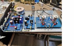
in attach the photo of a project I have develpped years ago and now available.
It can use some tubes and mainly 6H30 with fixed bias ( in the photo) or autobias just with little changing in jumpers.
The negative bias is done with a 7915 the a trimmer. And HT is ss regulated ( mandatory)
It works great without any problem with this solution
Walter
Attachments
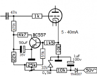
In attach the schematic
It is a simply CF but with the possibility to change some tubes changing the jumper fo filaments
Family as ecc88/6H23/pcc88/6N6/6H30/12BH7/ECC82 etc.
With jumpers it is possible to have a fixed bias or autobias
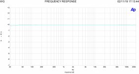
In addition the thd vs level; the 0 dB is 2 volt, +20 dB are 20 volts
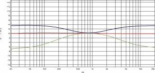
Then the frequency answer
tube is 6H30
Wallter
It is a simply CF but with the possibility to change some tubes changing the jumper fo filaments
Family as ecc88/6H23/pcc88/6N6/6H30/12BH7/ECC82 etc.
With jumpers it is possible to have a fixed bias or autobias
In addition the thd vs level; the 0 dB is 2 volt, +20 dB are 20 volts
Then the frequency answer
tube is 6H30
Wallter
Attachments
Last edited:
waltube,
Thanks for posting the schematic.
The input stage appears to be a combination of Self Bias and Fixed Adjustable Bias.
I do not see a stage that is only fixed bias.
But I do not know the resistance value of the cathode resistor. It appears to be large enough to require the option of using one or more bypass caps (the pads that seem like they might be jumper-ed or not). Most would not use a bypass cap of the resistance value is very low).
That indicates to me it is using combination bias.
I see a way to jumper out the fixed bias, but I do not see a way to jumper out the self bias.
Your Cathode follower is self biased, the un-bypassed cathode resistor is self bias.
From there, it is connected to a coupling cap to the output.
Oh, just for others who read this, what you call auto bias, I call self bias.
Last edited:
I assure you that you can configure the input stage in two indipendent way.
Fixed and self bias ( if you prefer.)
Just with the combination of jumper that can fix or amovible and reversibke in case.
In case I can explain you the way If you can't see the two method.
ps= I modified the post
Fixed and self bias ( if you prefer.)
Just with the combination of jumper that can fix or amovible and reversibke in case.
In case I can explain you the way If you can't see the two method.
ps= I modified the post
Last edited:
I forgot to mention the possibility with three jumepr /channel to insert the tone control
In attach the schematic and the board
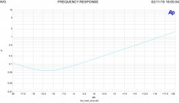
In addition the response with 6N6
The the esaltation and attenuation is not very hard
Walter
In attach the schematic and the board
In addition the response with 6N6
The the esaltation and attenuation is not very hard
Walter
Attachments
")
- Status
- This old topic is closed. If you want to reopen this topic, contact a moderator using the "Report Post" button.
- Home
- Amplifiers
- Tubes / Valves
- Fixed Bias on 6H30