Hello all,
I'm planing on building the 2007, tube rectified, version of the Musical Machine and I am having a little bit of trouble understanding part of the power supply side of the schematics. I'm pretty new to reading circuit diagrams so if I miss anything silly I'm sorry, still getting the hang of things.
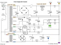
Basically my problem is, that after I got everything straight in my head I actually decided to read the title and saw that the power supply seems to be just for one channel. So my question is: do I duplicate parts of the power supply circuit? The title seems to suggest that everything but the T3 circuit needs to be duplicated for a stereo amp. However looking at images of already built amps makes me think that's not true.
Otherwise I am pretty confident on how this amp goes together, but I'd appreciate any other general advice on parts or how to construct this amp. I'll do some reading around here anyhow and I also have the WayBack Machine to look at Poindexter's old website for parts advice and whatnot.
I'd appreciate any help greatly.
Cheers.
I've attached a copy of the plans I am using.
I'm planing on building the 2007, tube rectified, version of the Musical Machine and I am having a little bit of trouble understanding part of the power supply side of the schematics. I'm pretty new to reading circuit diagrams so if I miss anything silly I'm sorry, still getting the hang of things.
Basically my problem is, that after I got everything straight in my head I actually decided to read the title and saw that the power supply seems to be just for one channel. So my question is: do I duplicate parts of the power supply circuit? The title seems to suggest that everything but the T3 circuit needs to be duplicated for a stereo amp. However looking at images of already built amps makes me think that's not true.
Otherwise I am pretty confident on how this amp goes together, but I'd appreciate any other general advice on parts or how to construct this amp. I'll do some reading around here anyhow and I also have the WayBack Machine to look at Poindexter's old website for parts advice and whatnot.
I'd appreciate any help greatly.
Cheers.
I've attached a copy of the plans I am using.
Attachments
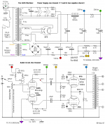
Interesting you should post this just now as I'm collecting the parts to build an amp to this very schematic. To answer your question, both channels do indeed share a common power supply.** The line at the top of the schematic confused me also, but a look at some shots of the interior confirmed just the one supply.
I'll be working in a few changes, most notably the omission of the input selector and volume control. I'll also be adding two more bias taps to allow for independent biasing of all four tubes. That way I can use most of the tubes I have on hand without having to worry about finding or buying "matched pairs" - which is usually more costly in addition to being a minor irritant.
**Edit: Eli is probably right with regard to the 5Y3 shown. Poinz's production versions apparently used a 5AR4 rectifier, which would allow for more current draw. Couple one of those with a power transformer capable of 150 mA or more and you should be OK. The use of the two separate transformers points to its "parts bin" lineage. Good catch!
Last edited:
The low voltage supply is shared. You have to build a B+ supply for each channel. The 5Y3 rectifier can supply 125 mA.
By that I think Eli means you need two 5y3s for both channels, or one 5y3 for each channel.
Eli, please correct!
Last edited:
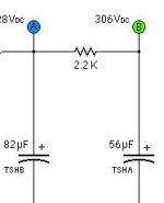
Ah, thanks Eli that makes sense. So the only thing I have to double up on are the caps before the high voltage outputs?
As for what you said Mr Zenith, I came across this version of the plans from your post so thank you for asking about them. I hadn't thought of having individual bias pots, but that makes sense. Might add that to my schematics as well.
Here's a picture of the caps I am thinking of as well as the type of amp I think the plans depict.
Attachments
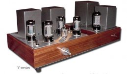
Aye, I see the source of my confusion. Yes, Eli is absolutely correct with regard to the schematic shown. The problem is that all of the existing pictures of this amp are of the production versions with the single supply. These were more "polished" than the originals, which (according to the original website) were mostly built from parts the designer had on hand.
To confuse things even further, I'm using one of those Antek toroidal transformers with dual heater and HV windings. My goal is to breadboard the circuit first to determine which configuration works best. Will it be one single tube-rectified full-wave supply with the windings in series, or will it be two separate bridge-rectified circuits? We'll soon find out! Heck, I might even go nuts and throw in four more tubes for a push-pull parallel deal (I have a pair of 5k transformers kicking about somewhere).
To confuse things even further, I'm using one of those Antek toroidal transformers with dual heater and HV windings. My goal is to breadboard the circuit first to determine which configuration works best. Will it be one single tube-rectified full-wave supply with the windings in series, or will it be two separate bridge-rectified circuits? We'll soon find out! Heck, I might even go nuts and throw in four more tubes for a push-pull parallel deal (I have a pair of 5k transformers kicking about somewhere).
Okay, so from my understanding I need:
2 heater circuits,
1 Bogen T362-3,
1 5Y3 tube,
1 Inductor,
2 sets of 328VDC and 306VDC outputs,
a total of 2 6GK5 tubes
and a total of 4 6V6 tubes.
Does that sound correct? Pretty sure I am confusing myself here.
I thought the old sand Power Supply version was the one referred to on Poindexter's website. Let me know if you find anything interesting in that breadboarding. I am a bit unsure which plan is the ideal plan to use. I know of the 2006 sand version, 2007 tube rectified and the 2008 tubeless PS.
Per the graphic, 2X Bogen T3662-3 power transformers are needed!
I highly doubt those Bogen items can be sourced. If Hammond products are available in "Oz", 1X of their model 373FX can be adapted to the project. A pseudo dual mono, instead of a true dual mono, B+ setup would be employed. Rectify the 373FX's 325-0-325 VAC winding with a 250 mA. 5U4GB. Between the 5U4's lower forward drop than that in a 5Y3 and tweaking the value of the 1st filter cap., the B+ rail voltage will be fine. The 373FX's 5 VAC winding has a CT. So, take the "raw" B+ from that CT, instead of socket pin 8, for lowest residual hum.
Follow the shared 1st filter cap. with separate (1/channel) 10 H. chokes and CRC filter networks. Hammond's 159P seems suited to the task at hand.
BTW, the AMVECO part is also a problem. That item has been discontinued. Perhaps, a NOS specimen can be sourced. The 373FX has a bias tap that can be 1/2 wave rectified and filtered. However, that only takes care of O/P tube control grid bias requirements. A means must be found for generating the negative rail the LTP constant current sink (CCS) setups require.
I highly doubt those Bogen items can be sourced.
If Hammond products are available in "Oz", 1X of their model 373FX can be adapted to the project. A pseudo dual mono, instead of a true dual mono, B+ setup would be employed. Rectify the 373FX's 325-0-325 VAC winding with a 250 mA. 5U4GB. Between the 5U4's lower forward drop than that in a 5Y3 and tweaking the value of the 1st filter cap., the B+ rail voltage will be fine. The 373FX's 5 VAC winding has a CT. So, take the "raw" B+ from that CT, instead of socket pin 8, for lowest residual hum.Follow the shared 1st filter cap. with separate (1/channel) 10 H. chokes and CRC filter networks. Hammond's 159P seems suited to the task at hand.
BTW, the AMVECO part is also a problem. That item has been discontinued. Perhaps, a NOS specimen can be sourced. The 373FX has a bias tap that can be 1/2 wave rectified and filtered. However, that only takes care of O/P tube control grid bias requirements. A means must be found for generating the negative rail the LTP constant current sink (CCS) setups require.
A means must be found for generating the negative rail the LTP constant current sink (CCS) setups require.
FYI, the "24" VAC a Hammond 1182K12 toroid feeding a "full wave" doubler working into a stack of 2X 120 μF. caps., instead of the diode bridge plus 56 μF. cap. Poinz's graphic shows, would yield the requisite result.
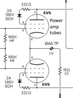
The 6GK5 is not a twin triode. An instrument matched pair of tubes is needed to form a LTP.
Attachments
Last edited:
Here we go again . . .
The 6V6 is being used as an Audio Power Output tube, not an RF Power Tube.
The diodes in the screens are not needed (unless they are Zener diodes, and they are not drawn that way).
Prevent discontinuity of current, take the diodes out.
If course Really Bad 6V6 tubes might have lots of Reverse screen current.
If they do have lots of Reverse screen current, than throw out the bad ones, and get good 6V6 tubes.
Last edited:
Oh, no we don't! Agreed completely. This is the only audio-related schematic I've ever seen those g2-anode diodes on before, and Tubelab's explanation of their existence there makes sense. There's nothing magical about them, so I'll be leaving them out of mine for sure - or at least I'll be using them where they belong, like the power supply.
Agreed completely. This is the only audio-related schematic I've ever seen those g2-anode diodes on before, and Tubelab's explanation of their existence there makes sense. There's nothing magical about them, so I'll be leaving them out of mine for sure - or at least I'll be using them where they belong, like the power supply.I purchased an Antek AN-0124 for this. It's $10 US, and I can tie the secondaries in series without the hassle of pootling about with a voltage doubler. Not that there's anything wrong with that of course, but I'm working toward a relatively clean build, physically speaking (at least that's the idea).A means must be found for generating the negative rail the LTP constant current sink (CCS) setups require.
Last edited:
I purchased an Antek AN-0124 for this. It's $10 US, and I can tie the secondaries in series without the hassle of pootling about with a voltage doubler.
An excellent decision on your part. However, the OP is in Australia and I highly doubt that party wants to pay shipping from NJ to "Oz". OTOH, both Australia and Canada are Commonwealth members, which might make Hammond manufactured items less of a hassle.
The Antek 100VA 250V transformer will power this with a solid state bridge rectifier; doesn't have a 5V winding anyway. With a tube rectifier, you'll need at least a 150VA transformer due to the poorer transformer utilization of the full-wave center-tap rectifier. Plus it needs higher voltage due to the tube's voltage drop. Using a small capacitor before a choke input filter as in the original can bump up the voltage at the expense of regulation; but since it's class A, regulation isn't as important. A single 200 mA choke can be used, or you can split the supply and use two 100 mA chokes. Nothing magic about the 10 Hy value - a smaller one can can give the same filtering if the output cap is increased proportionally.
A larger Antek transformer can be used with a 6V rectifier like 6BY5 if you must have a tube rectifier.
A larger Antek transformer can be used with a 6V rectifier like 6BY5 if you must have a tube rectifier.
If you are purchasing a new B+ transformer, then first calculate the needed rms voltage;
Include the DC drops of the choke DCR; the primary DCR x step-up ratio; Secondary DCR [1/2 or full, depending on center tapped or bridge rectified], and rectifier drop (especially if you use a tube rectifier).
Multiply the total DCR x the DC current draw, to calculate the total voltage drop.
Choke input filter's DC voltage out is 0.9 times the rms voltage (minus all the voltage drops listed above).
If you use real Choke input filtering, be sure to obey the Critical Inductance rule:
350/DC mA draw (60 Hz Mains Power).
420/DC mA draw (50 Hz Mains Power).
Example:
60 Hz Mains Power
For a 50mA DC output, 350/50mA = 7H
Use a 10H choke, to be sure (some chokes are not created equal, some are better than others).
If the inductance is less than the critical inductance rule, then . . .
The 0.9 x rms is not correct (will be > 0.9 x rms)
The B+ secondary will run hotter
The B+ will not be as well regulated
I use choke input filtering whenever I can, and add an extra RC filter for the last filter stage (to power the input stage tube).
Last edited:
The Antek AN-0124 Mr_Zenith mentioned is suited only to generation of the negative voltages used by the circuitry.
It seems clear to me that the OP wants vacuum rectified B+. Given that "reality", I suggested a Hammond power trafo and 5U4GB rectifier. FWIW, Hammond products appear to be widely available in Australia and it is possible to execute this build with 100% new magnetics from the Canadian manufacturer.
It seems clear to me that the OP wants vacuum rectified B+. Given that "reality", I suggested a Hammond power trafo and 5U4GB rectifier. FWIW, Hammond products appear to be widely available in Australia and it is possible to execute this build with 100% new magnetics from the Canadian manufacturer.
Sorry for the delay in the reply here, has been a bit to process. I'm not strictly married to the idea of a tube rectified setup as I imagine that it won't have any real impact on the sound of the machine.
You are right about the prices of some of those transformers over here Eli, One of the AnTek transformer was going to cost me $40 + $80 shipping. I have been looking at the 2008 plans as well, they look a bit easier for me to understand honestly (although the at least one of the transformers may be hard to get ahold of over here).
Thanks for all the help from everyone I think you've saved my from making some weird mistakes.
I'll attach the 2008 power supply. As far as I can see there are still parts I'd have to duplicate for stereo, despite the title, and I am unsure exactly what Rdrop refers to.
I'll do more reading here as soon as possible. Bit busy at the moment so sorry if I'm a bit slow to respond.
Cheers.
Attachments
The diodes in the screens are not needed (unless they are Zener diodes, and they are not drawn that way).
Prevent discontinuity of current, take the diodes out.
Ah alright that's an easy change I'll attach an image just to double check I have the right diodes in mind. Thanks for that note.
Attachments
Rdrop is a voltage dropping resistance. Remember, 6.3 VAC is nominal. Dropping is used to make things "just so", if necessary. In general, it is desirable for the heaters to be operating at nominal -10%/+5%.
Hammond stuff may be no great bargain in "Oz", but it is (quite importantly, IMO) readily available. Let's enumerate a 100% Hammond list of magnetics for a stereoblock build that employs vacuum rectified B+.
1 - 373FX EI power transformer for B+ and heaters
1 - 1182K12 toroid power transformer for generating negative voltages
2 - 159P B+ filter chokes, with 1 inductor per channel.
2 - 1609A push/pull output transformers.
BTW, the 6.3 VAC winding of the 373FX has a center tap. So, there is no need to "synthesize" a CT with 2X 330 Ω resistors.
Ah okay, that's easy, just got to aim for 6.3V.
As for the Hammond parts, they all make sense to me, but they add up to about $600 AUD, which seems a little steep in comparison to the diode rectified design. I'll use those filter chokes at the very least, I am pretty happy with the price on them.
As for the Hammond parts, they all make sense to me, but they add up to about $600 AUD, which seems a little steep in comparison to the diode rectified design. I'll use those filter chokes at the very least, I am pretty happy with the price on them.
- Status
- This old topic is closed. If you want to reopen this topic, contact a moderator using the "Report Post" button.
- Home
- Amplifiers
- Tubes / Valves
- 6GK5 Musical Machine Help