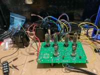
I'm building a Tubelab SPP that is currently mocked up before put in a chassis.
I also just finished Jan's Autoranger so thought that it could be interesting to run some measurements on the SPP.
I have 3 quad's -- new JJ's from AES, NOS Telefunken that were found sealed by a member here, and Matsushita 6BQ5 that I bought off a Japanese auction site.
I tried 3 different 12AT7's (all NOS) and results were similar.
SPP is built with Hammond 1650FA OPT's, using UL. B+ around 315V
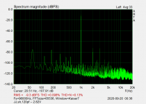
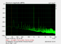
I ran an FFT at both 1W output and right before clipping (about 10W)
The test results were very surprising...
The Telefunken had highest overall THD but it was primarily 2nd harmonic. It's 3rd harmonic was significantly lower, while the other 2 pairs had similar amounts of h2 and h3.
The Matsushita had surprisingly low THD .. the numbers look almost too good to be true.
What do you think of these results?
EDIT: These results were incorrect. Updated numbers: https://www.diyaudio.com/forums/tub...easurable-distortion-makes-2.html#post6348638
I also just finished Jan's Autoranger so thought that it could be interesting to run some measurements on the SPP.
I have 3 quad's -- new JJ's from AES, NOS Telefunken that were found sealed by a member here, and Matsushita 6BQ5 that I bought off a Japanese auction site.
I tried 3 different 12AT7's (all NOS) and results were similar.
SPP is built with Hammond 1650FA OPT's, using UL. B+ around 315V
I ran an FFT at both 1W output and right before clipping (about 10W)
The test results were very surprising...
The Telefunken had highest overall THD but it was primarily 2nd harmonic. It's 3rd harmonic was significantly lower, while the other 2 pairs had similar amounts of h2 and h3.
The Matsushita had surprisingly low THD .. the numbers look almost too good to be true.
Code:
		1W 	10W
JJ		0.1%	0.63%
MAT		0.05%	0.21%
TFK		0.36%	0.88%
What do you think of these results?
EDIT: These results were incorrect. Updated numbers: https://www.diyaudio.com/forums/tub...easurable-distortion-makes-2.html#post6348638
Attachments


Last edited:
Yea,
The schematic can be found here: https://www.diyaudio.com/forums/tubelab/271702-tubelab-spp-schematic.html#post4264971
and further info: Simple Push-Pull (SPP) Board | Tubelab
The schematic can be found here: https://www.diyaudio.com/forums/tubelab/271702-tubelab-spp-schematic.html#post4264971
and further info: Simple Push-Pull (SPP) Board | Tubelab
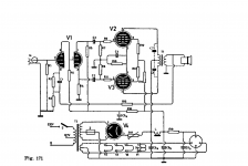
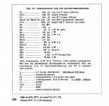
Might as well post a design that was much in favour in The Netherlands around 1958.
It is possible to replace the single shared cathode resistor with each EL84 having a resistor of 250 Ohm, 2 Watt and a 100uF 25V capacitor. Personally I prefer stay with the cathode bypass around this value, too large can lead to instability.
There was a remark to use a wirewound resistor for the feedback since carbon resistors can exhibit a different value at a different voltage.
Attachments
Last edited:
Feedback disconnected?
Resistor load?
How well idle balanced is each pair when tested, given there is no trim (and are your resistors 1%)?
Do you get the same result for a pair if you swap tubes to the other side?
It would be interesting to know how matched the tubes were, both current ( voltage at cathode at idle i the circuit shown ) and Gm at the operating point ( has to be measured somewhere else).
Feedback was connected.
Load resistor was an 8ohm 100W.
Cathode resistors are Mills MRA-5 270R 1%.
The JJ are brand new and all 4 should be factory matched.
The Telefunken were tested with a RoeTester and matched based on plate current (both 95% of new)
No idea about the Matshushita.
I measured the voltage at the cathode multiple times, but didnt write the exact value during the test. They were typically between 10.3-10.8 (38-40mA)
I can re-run the tests, this time in the other channel, with the second pair from each quad to see if the results are consistent.
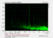
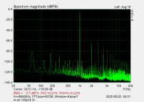
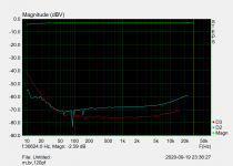
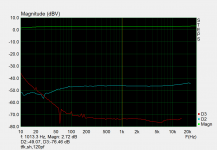
Here is also a frequency response graphs of Tfk and Matshushita. The h2/h3 distortion profile is very different between the 2.
Attachments
The tubes has no frequency preferences, the amp has.
The test is disturbed by the NFB, it tries to correct and succeeds more or less. Depending
to how the feedback is tubes it might fit one or another.
Better would be to disconnect feedback during the test, this will show how it really
distorts,
When tubes are mounted, it would be very enlightening to record both cathode voltages,
this is a good measure of how matched they are as bias concerns.
Measuring AC signal on the plates will tell how Gm is matched.
Good points.
The frequency response is of the amp, but it the distortion profile is different depending on which output tube was used.
The Japanese tube is lower but h2 and h3 are close where as the Tfk had significantly more h2.
I'll re-run the tests without gNFB, with the other pair and also note the cathode voltages
As an indication of the variation of raw distortion that can occur in a PP amp due to changing tubes:
https://www.dalmura.com.au/static/The%20Williamson%20Type%20amplifier%20brought%20up%20to%20date.pdf
https://www.dalmura.com.au/static/The%20Williamson%20Type%20amplifier%20brought%20up%20to%20date.pdf
Yes, I read that issue! https://www.tiffe.de/roehren/VTV/VTV08.pdf
OK so I retested the pairs, this time with and without gNFB, in both L & R channels.
Conclusion: I have no idea how I tested the first time around (maybe wrong setting on the autoranger) but those values were not correct at all!
With (what I think are now) proper measurements,
The JJ and Telefunken measure pretty close: 0.3% @ 1W and 1.5% @ 10W (no feedback) and 1% w/ feedback.
The Matsushita was not as good with 0.7% @ 1W and 2.5% @ 10W (no feedback) and 1.4% w/ feedback.
Tube bias (voltage across 270R cathode resistor) was:
JJ -- 38.8mA/39.8mA
Matsushita -- 37.4mA/37.9mA
Telefunken -- 39.2mA/39.8mA
So yes there are measurable differences but not as drastic as I initially thought.
Not sure if this translates to different sound or not.
My test setup is a bit of a rats nest so I will redo this once I have the amp all cased up
Last edited:
I haven't tried with speakers yet, its currently mocked up on my bench in the garage.
(It's quite a mess right now)
I did connect an iPod shuffle though with Sennheiser HD650's to the 8ohm tap with a 20R load resistor and it sounded really nice.
Only after I get it in a case, I'll bring it in and try with speakers.
(It's quite a mess right now)
I did connect an iPod shuffle though with Sennheiser HD650's to the 8ohm tap with a 20R load resistor and it sounded really nice.
Only after I get it in a case, I'll bring it in and try with speakers.
Attachments
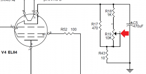
DIY TUBE BIAS SCHEME
The DIY Tube Dynaclone (no longer available) used this arrangement, see pic., one for each EL84 to adjust bias. The 470 ohm is a 2w the others 1/2 watt. Measure voltage across the 10 ohm res to calculate current. I did this on a SPP. Left out the cathode resistors for the EL84s on the PCB and put the adjustable bias components on a small perf board. Bypass cap stayed on the SPP board. It works well.
Cheers, Steve
Attachments
Thanks Tim and Steve.
Yes, generally I'm curious about the performance of the amp in different "modes" ... not sure if I'll do it with this PCB though, it was one of my nicest soldering jobs")
Was thinking of LED biasing, I know that George tried it with SY's recommendation but I don't know the details.
Simple Push-Pull (SPP) Board | Tubelab (towards the end)
Yes, generally I'm curious about the performance of the amp in different "modes" ... not sure if I'll do it with this PCB though, it was one of my nicest soldering jobs
Was thinking of LED biasing, I know that George tried it with SY's recommendation but I don't know the details.
Simple Push-Pull (SPP) Board | Tubelab (towards the end)
- Status
- This old topic is closed. If you want to reopen this topic, contact a moderator using the "Report Post" button.
- Home
- Amplifiers
- Tubes / Valves
- EL84 measurable distortion between different makes