Hi,
my latest project was the Trion MK2 SE EL 34 tube amp and this amplifier works without problems since a year now.
My wish is to build a new amplifier - also single ended with a bit more power.
Two years ago I built a pair of "Statements" loudspeakers from the Hobby Hifi magazine - 95db efficiency, two ways with a 15" PA Monacor speaker and a celestion cdx horn.
I'am interested in building a 6C33C SE amplifier and now I'am looking for a good and simple schematic.
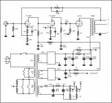
I found this after a long search in the forum:

but also different schematics with different driving stages and power supplies.
I also have two NOS D3A tubes and a lot of 6P15P-EV.
Maybe there are some new schematics out there or some good proven ones - please let me know.
Felix
my latest project was the Trion MK2 SE EL 34 tube amp and this amplifier works without problems since a year now.
My wish is to build a new amplifier - also single ended with a bit more power.
Two years ago I built a pair of "Statements" loudspeakers from the Hobby Hifi magazine - 95db efficiency, two ways with a 15" PA Monacor speaker and a celestion cdx horn.
I'am interested in building a 6C33C SE amplifier and now I'am looking for a good and simple schematic.
I found this after a long search in the forum:
but also different schematics with different driving stages and power supplies.
I also have two NOS D3A tubes and a lot of 6P15P-EV.
Maybe there are some new schematics out there or some good proven ones - please let me know.
Felix
Attachments
This is the way to go. You definitely don't need a 200H choke, and I wouldn't recommend the Valab choke. A 50H/20ma plate choke would be more than adequate and much easier to find from more reputable vendors.
Hi Felix.
Because you have a lot of 6P15PEV, and if you don't have anything against pentode driver, why not try the old idea "6P15P/SV83/EL84 pentode driver for 300B or 6C33C".
With about 1.3Vrms input voltage you will have about 75Vpeak (150Vpp) output voltage from pentode 6P15PEV driver. That's enough to have about 12Wrms output power from the 6C33C
Caution:
RE: The Schematic in Post # 1.
There are 3 inverting stages.
The global negative feedback is taken from the 8 Ohm Tap.
You have to swap the leads on the output transformer primary.
(make the plate signal versus output tap phase inverted).
Otherwise you have an Oscillator; you will not have an Amplifier.
Post # 2 schematic,
A high impedance D3A in pentode may have trouble driving the choke inductance at low frequencies.
A high impedance D3A in pentode may have trouble driving the choke distributed capacitance at high frequencies.
In order to get the inductance high enough, a very large number of turns are required (and lots of laminations). Otherwise, the limited inductance will rolloff the low frequencies.
But the turns will have to be in multiple sections, with very large spacings between each section (like specialized sectioned RF chokes). Otherwise the distributed capacitance will rolloff the high frequencies.
Schematic Post # 3 and Post # 5.
Drawing mistake:
The driver tube grid and screen are drawn to be one grid.
You can not apply signal, and resistor to B+ to the same grid, and expect it to work.
Does anybody actually check any of these schematics, before they post them? ? ?
Newbees beware!
Build it as drawn, and weep!
Drawing mistake:
The driver tube grid and screen are drawn to be one grid.
You can not apply signal, and resistor to B+ to the same grid, and expect it to work.
Does anybody actually check any of these schematics, before they post them? ? ?
Newbees beware!
Build it as drawn, and weep!
Last edited:
Post # 2 schematic,
A high impedance D3A in pentode may have trouble driving the choke inductance at low frequencies.
A high impedance D3A in pentode may have trouble driving the choke distributed capacitance at high frequencies.
The D3A is triode strapped in that schematic. Driving the choke will not be a problem!
Yes. The schema from DHTRob site needs "dots" at the connection points. I also at first thought it was a fashion pentode.
BTW, I have a D3a-6C33C SET as my second amp in the weekend house. I also tried choke load on triode mode D3a (primary of LL1660) and then gyrator (Ale Moglia version).
I stayed with the gyrator because he doesn't play worse, lighter, cheaper, he needs less space ....
BTW, I have a D3a-6C33C SET as my second amp in the weekend house. I also tried choke load on triode mode D3a (primary of LL1660) and then gyrator (Ale Moglia version).
I stayed with the gyrator because he doesn't play worse, lighter, cheaper, he needs less space ....
Attachments
1. Ok, I missed the "missing dot" in Post # 2.
A very expensive D3A running a very expensive choke; or why else spend so much money?
Because: Good is Not Cheap; and Cheap is Not Good.
Can anybody tell me how much a D3A will cost me here in the US?
Thanks!
Using a driver plate Choke load (with air gap), and any of the following will be very sensitive to hum:
Magnetic Steel Chassis
Close spacing to Power transformer and/or to B+ choke (especially if it is Choke Input B+)
Orientation of the Choke plate load, versus power transformer and B+ Choke
2. Now, look at the schematic of Post # 3.
That is the first time I have ever seen such a driver tube:
It has a filament, a cathode, a plate, Only One Grid, and Beam Formers.
A combination g1 / g2 grid? That does not work as drawn.
We 'probably' know what the draftsman meant, but only by assuming what he meant.
Last edited:
You bring up a good point, it's probably more appropriate to pair the 6C33 with a 6J52P instead of a D3A.
I agree. D3a and some other really good tubes are unnecessarily overpaid.
But 12-15 years ago it was all at a bargain price (in Pollin.de for example). In those days some other small signal tubes were more interesting. But not for everyone.
But 12-15 years ago it was all at a bargain price (in Pollin.de for example). In those days some other small signal tubes were more interesting. But not for everyone.
- Home
- Amplifiers
- Tubes / Valves
- simple 6C33C schematic