Oh no, another Zintolo's thread about that ####### Baby Huey?
Yes. This time with building notes.
As some of you probably know, before assembling the pcbs I decided to study the project and I got bored alot of you with silly questions and pedantic arguments. I'm sorry for that, but I'm glad it helped me understanding (partially, as I'm sure I'm still missing alot) the circuit and the design process that lead there.
Everything started from Yves Monmagnon "Dissident Audio" ECL86 amp:
Push Pull ECL86/6GW8
Then it has been further developed by Ian "Gingertube" by substituing the ECL86s with a 12ax7 and two EL84 (that are equivalent to the ECL86 indeed).
Then UL has been integrated (instead of the original and preferred by Ivesm pure pentode) to reduce the THD of the EL84s, but with Hammond trafos with 43% UL taps, the ratio is not the right one (see here: http://www.oestex.com/tubes/Rudolf Moers - Appendices.pdf and here: UL for EL84. 22-24% is better than the dogma....40% is lowest distortion.... ).
Then it has been modified the CCS on the tail of the PI to increase the AC impedance and so improve the balance of the phase inverter. Total current of the CCS passed from original Yvesm value of 1 mA to 1,2 mA and no more than 1,4 mA (700 uA per side).
Then it has been applied the trick to reduce 3rd harmonic content: EL84 Amp - Baby Huey
Then the output tubes have been switched from cathode bias to fixed bias to improve the recovery when overloaded.
Then powerdrive has been applied, with a simple resistor on the mosfet.
Final developement has been to increase the driving capability of the powerdrive by applying a CCS instead of the simple resistor to load the mosfet of the Powerdrive.
About R33 and R38:
to fully drive the EL84 I need around 25 Vpp (a bit more if I want to reach AB2) up to ten times (to be conservative) the bandwidth, so 200 kHz, so slewrate will be:
2 x pi x f x V = 2 x 3,14 x 200 kHz x 25 = 31,4 V/us
One EL84 has an input capacitance of 11 pF (let's say 15 considering wiring?).
C = i x dt / V
dV/dt = 31,4 V/us
then
15 pF = i / slewrate
so
i = 15 pF x 31,4 V/us = 470 uA
The current of the CCS is 0,7 / R33 (or R38), so we'll need that resistor to be less than 1.5 kOhm. I will keep the original 390 Ohm.
Powerdrive AC voltage supply
Being the negative side of the PI's CCS connected with the negative rail of the Powerdrive circuit, the voltage is set by this one at 3 times the bias voltage ( EL34 Baby Huey Amplifier ).
So for a EL84 amp with approximately -12 Vdc it will be around -35 so, multiplying by squared root of 2, a 50 Vac winding is needed to supply it (it's called BIAS on the pcb).
About R16 and R17:
On the BOM and the PCB they are shown as 1.6 kOhm and 1 kOhm respectively, but this is due to a very early version of the Baby Huey, not the current one.
The guideline is to keep the current of the led of the PI's CCS between 2 and 5 mA, preferibly towards the lower value. In both versions, EL84 and derived EL34, R16 is around 1.5 times R17. I still don't know why, but I'll keep this proportion.
So considering the small losses in D5&R28 plus the drop due to the led, we have around -33 Vdc to be dropped by R16 and R17 with around 2 mA.
Then R16 + R17 becomes 33 Vdc / 2 mA = 16.5 kOhm. Then I decided to have R16 = 10 kOhm and R17 = 5.6 kOhm. This leads to around 2.1 mA.
About R3 and R4:
On the BOM and the PCB they are shown as 1 kOhm, but this is quite low as a value.
The old guidelines for triodes were to use 8/gm to set the grid stopper value, so with a 12AX7 which gm is 1.6 mA/V the value would be around 5 kOhm. In my guitar amps I always use at least 10 kOhm because gm of the tubes goes down with age, and I want to be sure there are no issues even when tubes are almost gone.
With an avarage value of 12AX7's input capacitance (Miller included) in the order of 150 pF, 10 kOhm gives a low pass filter with -3db point at 106.1 kHz. I would say it's plenty acceptable.
IMPORTANT NOTE: carbon comp here is the best choice, because they are the resistors with lowest capacitance and inductance, and that is what is needed in this position. I used carbon film, the second place in the choice.
About R7 and R8:
In the BOM they are 600 mW resistors, but they need to be 1 or 2 Watts, because of the voltage they see across them (remember that they are connected to the shunt feedback system that is directly connected to the primary of the output transformer.
Of course I noticed it only after I soldered all resistors, so by now I decided to install 2W metal oxide resistors on a pair of pcbs and keep the BOM ones on the other two pairs, in order to be able to check the differences.
On my experience with guitar amps, higher wattage on plates of preamps gives more dynamics and more definition to the sound (over there there's need to get higher THDs with specific harmonics), I'm curious to see if it applies to this scenario too.
About R14 and R15:
On the pcb they are shown as 270 Ohm, on the forum someone suggested to raise that value to 1 kOhm to be on the safe side. I'll start with 270 Ohm (originally gingertube used 33 Ohm) and I'll see how it will react. I would say that this value depends also on the working conditions of the tubes: with pentodes they must be higher (because screens have higher potential than anodes, so secondary emission is higher), then optimal 23% UL is in between, and 43% distributed load will need them lower. I'll use 23% UL connections and 270 Ohm by now.
About R20 and R21:
They are shown as 470 kOhm on the pcb, but I used 1 MOhm instead.
The reason is these resistors are part of the load seen by the PI (detailed description here: EL84 Amp - Baby Huey even if it refers to the old schematic without powerdrive), and even if the difference between 470 kOhm and 1 MOhm when in parallel with 64 kOhm is small, why make it worst?
I think the 470 kOhm value comes from the pre-Powerdrive indications, because that was the grid-leak maximum allowed resistor for EL84. Now it is no more, so 1 MOhm is better.
About C1 C2 and C5:
Here the value shown on the pcb is 220 nF. For C5 I remember it's the 1/100 rule based on the main power supply cap, so C6 in this case.
As for C1 and C2, this value is very high. I used 100 nF for all three because the coupling caps with 1 MOhm load will have an high pass filter with -3dB point at 1.6 Hz, so one order of magnitude lower than what can be heard.
I used the suggested Vishay Ero 1813 because I already used them for my guitar amps and I liked them, then I've seen some suggesting them for Hi-Fi as well, so before investing 10 € for a cap, I give them a try.
Suggestion on it?
In attachment you can see the boards with the standard R7 and R8 resistors, and with the 2W metal oxide ones.
Attachments
![IMG_2978[1].jpg](/community/data/attachments/789/789757-250911103b31d2dce8f7d2c9ded67840.jpg?hash=JQkREDsx0t)
About power supply requirements:
Based on the notes taken reading the thread, it is needed to have 320 to 330 Vdc on the primaries, with 100 mA on each side.
Yves used 0-235V with 100 Ohm in series (and cathode bias), compared to the 10 Ohm suggested for the Baby Huey. 0-230 Vac 120 mA per pcb seems to be recognized as perfect (250 mA per stereo amp).
Powerdrive needs 0-50 Vac and I would say 50 mA per pcb (100 mA per stereo amp) just to safely charge the capacitors, then the consumption will be very low.
Heaters need 0-6,3 Vac and (600 + 760 + 760 =) 2.2 A per pcb.
I would prefer to have 3 A per pcb and 6 A per stereo amp to be on the safe side.
About Output Transformer:
Looking at this document: http://www.oestex.com/tubes/Rudolf Moers - Appendices.pdf
And this one: http://primarywindings.com/wp-content/uploads/2017/04/Mullard-Circuits-for-Audio-Amplifiers.pdf (page 22-23)
It is interesting to see that the suggested impedance when using 20% taps is lower than in triode and also lower than in pentode, not something in between as I would have expected. So with 20% taps the suggested Raa is 6.6 kOhm instead of the most available 8 kOhm.However, Table 1 shows that there is little benefit to be achieved in respect of distortion by increasing the common-winding ratio beyond 0.2 and, because of the greater power-handling capacities possible, the circuits described in this book which use distributed loading are designed for output transformers having 20 % of the primary winding common to the anode and screen-grid circuits.
This is an interesting reading concerning the shunt feedback effects, that is one of the main parts of this amp:
Shunt Feedback - effect on input impedance
See also the reference to the Harman Kardon Citation II circuit:
Harman Kardon Citation II
Shunt Feedback - effect on input impedance
See also the reference to the Harman Kardon Citation II circuit:
Harman Kardon Citation II
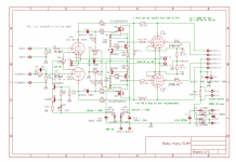
I uploaded the schematic in order to make it easier to understand all values and my comments:
About R11 and R12
Are 4.7 kOhm too high to be able to drive the EL84s into AB2? I would have expected one order of magnitude less, around 470 Ohm. It is a value used to avoid overloading the grids of EL84s that are not designed to work in deep AB2, but still be able to drive them better than without Powerdrive?
Anyhow I used 4.7 kOhm as suggested, by now.
About R13
Gingertube suggests 16.5 kOhm (two 33k in parallel), while Yvesm uses 12 kOhm with pure pentode. I've installed now a 15 kOhm, that is (15k/2) / 47k = 16% shunt feedback, in between 12.8% suggested by Yvesm and 17.5% suggested by gingertube. Also the screens will be connected with UL at 23%v that is in between pure pentode suggested by Yvesm and 43% used by gingertube.
About R27 or the choke:
Initially I was thinking about using a choke, as in some amps I've seen on the forum, but thinking more about it, reading this: CCS Amplifier & Aikido Active Long-Tail Phase Splitters
and doing some simulations on PSU Designer, it seems that the PSRR is very very good as is, and so I would keep the original design by Yves to use resistors instead of chokes by using a 10 Ohm 4 Watt resistor as suggested by the BOM.
About R39
This makes a voltage divider with trimmers R41 and R42 in parallel, so 15 kOhm in series with 25 kOhm. Having around -35 Vdc on the negative rail, the range of the trimmer is from 0 to -20 Vdc circa. I kept as it is on the BOM.
Attachments
About R1:
This is the global negative feedback resistor. In the Yvesm amp is 100 kOhm into 10 kOhm, in gingertube amp is shown as 12 kOhm on 470 Ohm but it is suggested not to connect it, working only with distributed load and shunt feedback. So the EL84s have local feedback only, and the 12AX7 has no feedback. This should keep IMD lower and simpler, so on low order harmonics mainly.
Other power supply possibilities
Another option that I would like to try is the following:
Connecting the heaters of the two pcbs in series, and supply them with a 12 Vdc 15 A SMPS module with integrated trimmer to set the voltage to 12.6 Vdc, like this one:
Trasformatore Alimentatore Adattatore AC110V 220V a DC12V 1A 2A 10A 15A 20A 30A 40A | eBay
Then use a smps dcdc converter like this one:
DC-DC Convertitore Boost 8 ~ 32V a 45 ~ 390V ad alta tensione ZVS Modulo Step Up BOOSTER | eBay
to supply the HV of each module. Ther producer says that at 320 Vdc it can supply continuously 100 mA.
Then it's needed to supply the PI's CCS and the Powerdrive with a dual voltage, and the same module i supplied also with that function:
Convertitore boost DC-DC da 8-32 V12 V a +- 45 V-390 V Carica condensatore ZVS | eBay
So with a total cost of 50 € we can supply the whole amp with stabilized and variable voltages, to find the sweet spot of the amp.
An update after some months. I've tested it and sounds very good, but I've still not found a proper definitive chassis for it.
R6 has to be removed it you in stall a volume pot.
R17 mod to red led: better high end. Change R16 to the value shown below depending on the negative voltage on C10. The suggestion is to have the negative voltage around three times the bias voltage of the tube (EG for EL84 you'll bias correctly at around -12V so C10 will need to be around -36V).
The goal is to fix the current through the leds at around 2 mA.
Code:
B- [V]	R17          	R16 [kOhm]
15	red led    	5,8
20	red led    	8,3
25	red led    	10,8
30	red led    	13,3
35	red led    	15,8
40	red led    	18,3
45	red led    	20,8
50	red led    	23,3
55	red led    	25,8
60	red led    	28,3
65	red led    	30,8
70	red led    	33,3
75	red led    	35,8
80	red led    	38,3
85	red led    	40,8
90	red led    	43,3
95	red led    	45,8
100	red led    	48,3
105	red led    	50,8
110	red led    	53,3
115	red led    	55,8
120	red led    	58,3
125	red led    	60,8
130	red led    	63,3
135	red led    	65,8
140	red led    	68,3
145	red led    	70,8
150 red led 73,3Great to see your progress! Thanks for your posts here. I honestly forgot about your thread here and just re-read it. Very good!
Thank you Francois! I'm pleased you appreciate!
I have to say that nowadays I would rephrase one of these posts: 43% UL and 8k Raa is not the wrong one, it's just another possible scenario. The other one (also suggested by Mullard datasheets) is 23%UL and 6k6 Raa.
Here I went to 23% and 8k Raa, a mix of the two. I get more damping than 6k6 Raa, more power than 43%UL, less linearity than 43%UL and 8k Raa.

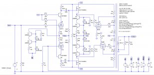
I attach here a modification to have a cascoded version of the PI.
These are the results at 15 Wrms:
These are the results at 15 Wrms:
Code:
Harmonic	Frequency	 Fourier 	Normalized	 Phase  	Normalized
 Number 	  [Hz]   	Component	 Component	[degree]	Phase [deg]
    1   	1.000e+03	1.542e+01	1.000e+00	   -0.94°	    0.00°
    2   	2.000e+03	2.008e-03	1.302e-04	  -86.84°	  -85.90°
    3   	3.000e+03	3.638e-02	2.359e-03	    7.21°	    8.15°
    4   	4.000e+03	1.262e-04	8.184e-06	  117.69°	  118.62°
    5   	5.000e+03	3.654e-03	2.369e-04	 -149.87°	 -148.94°
    6   	6.000e+03	1.021e-04	6.616e-06	  -78.02°	  -77.08°
    7   	7.000e+03	5.459e-04	3.539e-05	  103.90°	  104.83°
    8   	8.000e+03	1.827e-05	1.185e-06	   58.37°	   59.31°
    9   	9.000e+03	2.700e-04	1.751e-05	  -43.42°	  -42.48°
Total Harmonic Distortion: 0.237451%(0.237487%)
Attachments
EL84 BH with 6k6 43% OPT
Hi, as the OPT for BH is discussed here, please share your thoughts about EL84 BH variant with 6k6 43% UL transformer. According to EL84 Mullard data (https://frank.pocnet.net/sheets/129/e/EL84.pdf page D2) the output power with 6k Raa OPT should be around 10W (distortions 0.72%) for 300V supply. I'm wondering whether this option will work correctly with BH circuit. Any modifications should be applied (e.g. shunt feedback resistor value)? Highly appreciate your comments.Thank you Francois! I'm pleased you appreciate!
I have to say that nowadays I would rephrase one of these posts: 43% UL and 8k Raa is not the wrong one, it's just another possible scenario. The other one (also suggested by Mullard datasheets) is 23%UL and 6k6 Raa.
Here I went to 23% and 8k Raa, a mix of the two. I get more damping than 6k6 Raa, more power than 43%UL, less linearity than 43%UL and 8k Raa.
Hi stelark,
when you look at datasheets, you only find a specific way of using the tubes.
In this case you are looking for UL feedback only.
In a project like this one, the synergic effect of UL and local feedback have to work together and must be analysed together.
This is the reason I went for what is called the "maximum power" UL configuration together with a-g1 local feedback (often used alone to "triodize" the curves of the output tubes): simulating the combined feedback from a to g1 (24%) and g2 (23%) it gave me good results at almost twice the power you'll get with a-g2 feedback only.
43% UL has almost the same power at 6k6 and 8k Raa (the former has more current, the latter more voltage swing), but I prefer 8k (more linear, better damping, more "A" class, tube runs colder). Even 10k could work with 43% UL with not so much power loss.
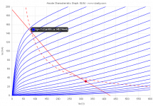
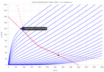
330V B+ together with 8k Raa and 23%UL gives a good transition into overdrive and brings the plate at around 50V with g1=0 (that means almost 20W), then 24% a-g1 feedback linearizes more and improves DF without stressing the phase inverter too much.
This is the best configuration I've found. Of course you can prefer different solutions based on your speakers, music preferences, mood et similia.
You can play with curves and loadlines using this tool:
Loadline calculator for power stages with reactive load - Vacuum Tube Amplifiers - DIY
when you look at datasheets, you only find a specific way of using the tubes.
In this case you are looking for UL feedback only.
In a project like this one, the synergic effect of UL and local feedback have to work together and must be analysed together.
This is the reason I went for what is called the "maximum power" UL configuration together with a-g1 local feedback (often used alone to "triodize" the curves of the output tubes): simulating the combined feedback from a to g1 (24%) and g2 (23%) it gave me good results at almost twice the power you'll get with a-g2 feedback only.
43% UL has almost the same power at 6k6 and 8k Raa (the former has more current, the latter more voltage swing), but I prefer 8k (more linear, better damping, more "A" class, tube runs colder). Even 10k could work with 43% UL with not so much power loss.
330V B+ together with 8k Raa and 23%UL gives a good transition into overdrive and brings the plate at around 50V with g1=0 (that means almost 20W), then 24% a-g1 feedback linearizes more and improves DF without stressing the phase inverter too much.
This is the best configuration I've found. Of course you can prefer different solutions based on your speakers, music preferences, mood et similia.
You can play with curves and loadlines using this tool:
Loadline calculator for power stages with reactive load - Vacuum Tube Amplifiers - DIY
- Home
- Amplifiers
- Tubes / Valves
- Slowly building three Baby Huey EL84 - with notes