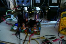
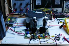
I dug my first proto UNSET board out of the junk box and made it live. I stuffed it with 36LW6's and tested it for proper function.
Then I attempted to answer two simple questions by using a little Edcor matching transformer for as phase splitter and wiring a push pull OPT across the output of both channels. The unset board is unchanged, except for reducing the bias from 120 mA per tube to 45 mA.
How many tubes will it take to get 500 watts. I now know that to be 6.
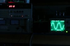
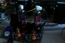
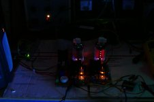
How much power (at 1KHz) can I squeeze through a $16 OPT designed for guitar amps by a battery charger company. I don't have this answer yet, but a pair of 36LW6's on 650 volts made the watt meter hit 253 watts in pretty severe clipping. THD is just under 4% at 200 watts, and 5% is at about 220 watts. I tried to take a few hand held pictures with the lights off, but that didn't work out too well. You can see the redness in the tubes at 220 watts, so 4 of them will not do 500 watts.
I started smelling something hot, so I powered down and touched a few things starting with the OPT. Yes one side was rather HOT....duh its between the output tubes and the load resistor that's eating those 220 watts (it was real hot and sitting on cardboard). The heat sink on the screen grid regulator (yes it's dropping 500 volts) was rather warm too.
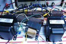
After this thing cools off, I may try an expensive OPT to see how it works. The little guy in between the two 1628SEA Hammonds was used for this test. I'll use a tripod this time too.
Then I attempted to answer two simple questions by using a little Edcor matching transformer for as phase splitter and wiring a push pull OPT across the output of both channels. The unset board is unchanged, except for reducing the bias from 120 mA per tube to 45 mA.
How many tubes will it take to get 500 watts. I now know that to be 6.
How much power (at 1KHz) can I squeeze through a $16 OPT designed for guitar amps by a battery charger company. I don't have this answer yet, but a pair of 36LW6's on 650 volts made the watt meter hit 253 watts in pretty severe clipping. THD is just under 4% at 200 watts, and 5% is at about 220 watts. I tried to take a few hand held pictures with the lights off, but that didn't work out too well. You can see the redness in the tubes at 220 watts, so 4 of them will not do 500 watts.
I started smelling something hot, so I powered down and touched a few things starting with the OPT. Yes one side was rather HOT....duh its between the output tubes and the load resistor that's eating those 220 watts (it was real hot and sitting on cardboard). The heat sink on the screen grid regulator (yes it's dropping 500 volts) was rather warm too.
After this thing cools off, I may try an expensive OPT to see how it works. The little guy in between the two 1628SEA Hammonds was used for this test. I'll use a tripod this time too.
Attachments
Last edited:
I knew Eagle from 1990 or so but did not see this "curvy" style before ..
That's just how I chose to draw it. There is an option to round the corners if you want.
As promised, here is a picture of the 21HB5A Sweep tube using Crazy Fdbk with Cathode drive. This is using just resistors for the feedback from the plate to G2 and G1, with NO Mosfet follower for the G2 current. Amazingly linear, so apparently the Vg2 at a constant fraction of plate V does work to get a constant resistive load at G2. However, the Fdbk resistor gets fairly hot delivering G2 current this way. And the voltage gain of the device is low. The cathode drive has to essentially deliver G2 type drive voltages.
To get good efficiency, one will have to use a Mosfet follower for driving G2 from the Crazy Fdbk resistors, so the Fdbk resistor can then be high value. The gain can be adjusted a little higher then, without the need to supply current to G2. But internal N Fdbk loop gain will be around 4X lower than series Schade (UnSet) due to the Vg2 level needed. The cathode drive will still need to supply G2 type voltage swing to develop the full power output. (more V stress on the cathode driver Mosfet versus UnSet)
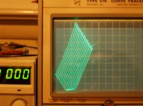
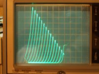
21HB5A TV Sweep tube: 50 mA/div Vert., 50V/div Horiz.
pic 1 is the Crazy Fdbk with cathode drive and G2,G1 N Fdbk
pic 2 is the series Schade to G1 with cathode drive, or UNSET as George calls it
Next, I want to try driving the cathode with another Sweep tube follower and a CCS tail (for just series Schade G1 mode). This should make for a symmetrical "triode" curve set. (due to similar gm of driven and driver tubes) Nearly straight in the middle sections, but curving off like an S at the limits. Soft clipping inherently.
To get good efficiency, one will have to use a Mosfet follower for driving G2 from the Crazy Fdbk resistors, so the Fdbk resistor can then be high value. The gain can be adjusted a little higher then, without the need to supply current to G2. But internal N Fdbk loop gain will be around 4X lower than series Schade (UnSet) due to the Vg2 level needed. The cathode drive will still need to supply G2 type voltage swing to develop the full power output. (more V stress on the cathode driver Mosfet versus UnSet)
21HB5A TV Sweep tube: 50 mA/div Vert., 50V/div Horiz.
pic 1 is the Crazy Fdbk with cathode drive and G2,G1 N Fdbk
pic 2 is the series Schade to G1 with cathode drive, or UNSET as George calls it
Next, I want to try driving the cathode with another Sweep tube follower and a CCS tail (for just series Schade G1 mode). This should make for a symmetrical "triode" curve set. (due to similar gm of driven and driver tubes) Nearly straight in the middle sections, but curving off like an S at the limits. Soft clipping inherently.
Attachments
Last edited:
UNSET as George calls it
UNSET refers to the particular amp I made with this circuit. If a SET is a Single Ended Triode amp, then what is a Single Ended amp that has no triodes, yet makes triode curves? UNSET.
The current P-P amp design got called the "offspring" since it fit the title of this thread. As of late last night the child has proved to be capable of "using the force" in a powerful way......and self destructing....the child is in surgery to replace a fried screen regulator......again.
I have referred to the tube / mosfet combo as the Compound Electron Device, or Composite Electron Device but that's mostly so that I can keep all my notes organized. The all get filed under "CED."
Yesterday afternoon I got out the first iteration of the UNSET board, fixed it up and tried driving the two channels out of phase through a P-P OPT. I bought 200 of these OPT's about 20 years ago to make guitar amps for $16 each. I still have several, so I use them for experiments that could end badly, and I have destroyed or damaged only two in 20 years. One erupted in flames when a cheap Radio Shack dummy load blew open at about 150 watts with 6LW6 tubes on 750 volts. The second became a magnet when a plate to ground arc due to a couple KV on a 300 volt feedback resistor, again 36LW6's at over 150 watts output. What's in the UNSET board? 36LW6's......
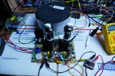
After a couple hours of beating on the setup produced no smoke, fireballs, or severe EMP events, I decided to swap out the $16 OPT for the Mother Of All OPT's. It's about the same size at the UNSET board and far heavier, rated for "400 watts @ 20 Hz, this beast should be able to wring more power out of the test amp. It's a 1250 ohm to 0-2-4-8 ohm transformer, but has been used successfully at 2500 ohms to 0-4-8-16 ohms up to 250 watts, so I hook it up.
The UNSET board is still completely stock. I haven't messed with any of the feedback paths or changed any parts, just turned down the idle current to avoid melting tubes at high B+ voltages.
Since the tubes behave as triodes, the idle current will be highly dependent on the B+ voltage. I had not tested 36LW6's at 2500 ohms before, even in pentode mode, so I started at 450 volts and 50 mA per tube and worked my way up to 630 volts at 35 mA, keeping the idle dissipation around 22 watts per tube / mosfet pair in roughly a 90/10 ratio. I was planning to try 650 volts at 33 mA (power supply max), but I never got there.
The results at 630 volts at 35 mA were far better than expected, and show that I could probably use a little less voltage in the big amp.
When I ran a frequency response at 100 watts test (the typical 1 watt test is just lame) some saturation was seen in the OPT.
Toroids, even big ones, are sensitive to DC and AC imbalance at low frequencies. I am using the primary of a little Edcor matching transformer as a phase inverter. It is running out of inductance and creating a drive imbalance, that I can't compensate for in the amp, so the LF results were slightly skewed. One output tube is obviously being driven harder than the other, as seen in the plates with the lights off. Even so the 100 watt +/- 3 dB frequency response is 11 Hz to 63 KHz. THD at 20 Hz was almost 4%, but remained below 1% from 46 Hz to 63 KHz. I have made measurements with these OPT's before and 63KHz is the upper 3 dB point in most cases (it's never been higher) so there are no HF limitations in the amp. Two LF poles with 1 megohm / 0.1 uF roll off the LF.
I ran a power VS THD and total current drawn from the power supply for the entire amp. Several watts were wasted in the screen regulator which dropped 630 volts down to 150 volts. Again, it blew up when attempting to hit 350 watts in severe clipping. The big amp will get a separate screen supply with current limiting to keep from killing tubes if the amp is driven to hard clipping for long periods of time. Who needs to run a 1 KW amp into clipping anyway?
Power THD total current
0.1W 0.430% 120 mA
0.5W 0.455% 120 mA
1.0W 0.462% 125 mA
2.0W 0.501% 135 mA
5.0W 0.569% 150 mA
10W 0.715% 180 mA
20W 1.15% 210 mA
50W 1.06% 310 mA
100W 0.880% 440 mA
150W 0.764% 550 mA
200W 1.366% 650 mA
250W 2.20% 750 mA
300W 6.88% unsure, PS went into I limit
350W power dropped off when screen reg blew.
As this test progressed the output tubes began to show red plate at 200 watts and got hotter at 250 watts. Peak efficiency was seen at 200 watts out, so the tubes don't like making 250 or more watts into 2500 ohms. 500 watts into 1250 ohms with 3 pair of tubes means each pair will see 3750 ohms and probably less B+.
If one channel drew 750 mA at 250 watts, two should draw 1.5 amps, or 945 watts, plus 202 watts for the tube heaters. The tube heaters will run from an SMPS, but the B+ supply is still unknown. Weight is the primary driving factor there. It all needs to draw less than 1800 watts to use a US spec power outlet (120 V @ 15 A)
The next step will be to make a proper phase inverter, then play with the feedback.
Attachments

What does the distortion spectrum look like?
I don't know right now. The PC that housed my M-Audio 24 bit 192 KHz sound card died maybe 2 years ago. That card had flat response out to 90 KHz and 80+ dB of dynamic range. It however fits in a PCI (not PCIe) slot which went extinct several years ago and is not supported in Windows 10.
I'm not going to hook test amps up to the $$$ Focusrite USB sound boxes that are in this PC and my studio PC, so I need to work something else out. I thing I have an ASUS Xonar board here somewhere, but I have never used it for any serious work.
I need to play musical PC's or maybe even musical motherboards to find something that works. For now THD is the only "yardstick" I have.
The AC imbalance is only present at low frequencies, but I tried to cheat by turning all the pots on the board to make the THD better at 20 Hz, but it got worse at 1 KHz.
As this test progressed the output tubes began to show red plate at 200 watts and got hotter at 250 watts. Peak efficiency was seen at 200 watts out, so the tubes don't like making 250 or more watts into 2500 ohms. 500 watts into 1250 ohms with 3 pair of tubes means each pair will see 3750 ohms and probably less B+.
If one channel drew 750 mA at 250 watts, two should draw 1.5 amps, or 945 watts, plus 202 watts for the tube heaters. The tube heaters will run from an SMPS, but the B+ supply is still unknown. Weight is the primary driving factor there. It all needs to draw less than 1800 watts to use a US spec power outlet (120 V @ 15 A)
630 volts squared divided by 2.5x1250 = 127 watts. Divided by 3 tubes is 42 watts, right at the plate dissipation rating. Doesn’t surprise me a bit that two get a little toasty. 63 watts is probably a little much, even for an LW6 - especially considering the screen dissipation may be on the high side. How much peak and average current was that drawing, when your regulator blew?
It doesn’t really need to stay under 15 amps of draw for sine waves. No amplifier in this power class will, even a class D, when you consider power factor. With music, even driven to clipping, current draw will probably stay under 15 amps. I run big solid state stuff all the time - some of which draw 85 amps from the line during a sine wave test. Breaker trips pretty quick at that level, but the music would have to be pretty damn distorted to trip a 20 amp breaker. Just do your testing with a dedicated 30 amp circuit. I’m sure you know how to wire one up.
How much peak and average current was that drawing, when your regulator blew?
I did not have a meter across the resistor in the screen supply, so I don't know whet the screen current was. After blasting the screen regulator fet twice in the original UNSET amp, I put a 1.5 K ohm 5 watt resistor in series with it's drain. Autopsy revealed that this resistor is what failed. The fet is still good. Next time I crank this thing up, I'll have a meter across this resistor.
Previous testing with this same board as a stereo SE amp in class A saw a brighter tube glow than seen in the right output tube here. Measured tube (plate and screen) dissipation at idle was about 70 watts. (470 volts across the tube at 150 mA ).
Working backwards from the known data here:
I was drawing 120 mA from the 630 volt supply at idle. The output stages were biased at 35 mA each, so 50 mA was consumed elsewhere in the amp (drivers and voltage dividers).
The amp was drawing 750 mA at full crank. 700 of that went into the output stage. About 10 volts is dropped in the OPT, and the cathode voltage is about 65 volts.
630-10 = 620 volts in the output stage * 700mA = 434 watts into the stage, and 250 watts out, meaning 184 watts are dissipated in the output stage.
There is about 65 volts across the mosfet and 555 across the tube at idle. Assuming no operating point shift, about 12% of the stage dissipation is in the mosfets, and 88% is in the tubes (162 watts total, 81 watts per tube. Yes, they are hot at full power.
The tubes idle at 562 volts (less drop in OPT) and 35 mA, under 20 watts.
The average dissipation at any reasonable listening level will be well below 40 watts per tube.
There are some who believe that an amp must be capable of running for 10 minutes continuously at it's full power rating in order to deserve that rating. I may or may not design to that concept. These tubes will eat 60 watts for 10 minutes without much complaint. In fact this particular pair spent a whole afternoon near 70 watts when I was listening to music in the SE version.
Further testing will be done to optimize the efficiency of the design for a pair of tubes at 250 watts into 2500 ohms (4 tubes per channel, not the likely choice) and a pair of tubes at 167 watts into 3750 ohms (6 tubes per channel).
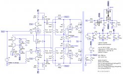
I have built an amplifier that was inspired by that RCA 50W circuit. The main differences are:
1. Using the CFB windings to the driver cathodes. Of course this requires a transformer with CFB windings.
2. Not using the plate to plate Schade loop, to prevent PS ripple from being injected into the driver stage and causing intermodulation sidebands with the signal.
3. Using a two-triode composite gain stage with local feedback to reduce input stage distortion, since input stage has less GNFB
4. Additional LF compensation to keep coupling cap values sane and extend LF loop gain and damping factor
5. 100W output with 4 x KT88 @ 270V screen instead of single pair 7027/6L6
6. Cascoded 6H30 instead of pentodes for drivers, though could have used 12HL7 or 12BY7 as well
7. Regulated supply to drivers and input stage.
8. Both inner and outer loops HF compensated
9. 24 dB of feedback around output stage (with 8 ohm loading)
The key to the RCA circuit's mystery is the multiple feedback loops. Nested feedback has a second order behavior, similar to two-pole compensation. It gets you more loop gain in the audio band, and has a 12 dB per octave rolloff, with an extra zero to return to 6 dB rolloff before reaching unity loop gain in order to maintain stability. There is a paper on this by Bruno Putzeys and a discussion can be found here.
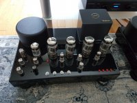
Sonic-wise, the first thing you notice with this amp is the bone-crushing bass, well controlled, not flabby at all. There is also excellent midrange clarity, you can crank the volume very high without getting harsh. The midrange remains clear even in the presence of strong LF content, which to me says low intermodulation distortion. This was something I did not expect with a pentode-connected output stage. My main concern is with the treble, but maybe this is just the beryllium tweeter in my speakers. They tend to be on the bright side, although without being edgy. Still, I am suspecting the issue could be either the silver mica compensation caps or the way I do the compensation in the outside loop (lead-lag across the input) which requires high resistance in series with the input. I may also reconfigure the input stage to use diff amp versus the feedback pair plus cathodyne in order to improve PSRR.
Attached is an image of the amp.
1. Using the CFB windings to the driver cathodes. Of course this requires a transformer with CFB windings.
2. Not using the plate to plate Schade loop, to prevent PS ripple from being injected into the driver stage and causing intermodulation sidebands with the signal.
3. Using a two-triode composite gain stage with local feedback to reduce input stage distortion, since input stage has less GNFB
4. Additional LF compensation to keep coupling cap values sane and extend LF loop gain and damping factor
5. 100W output with 4 x KT88 @ 270V screen instead of single pair 7027/6L6
6. Cascoded 6H30 instead of pentodes for drivers, though could have used 12HL7 or 12BY7 as well
7. Regulated supply to drivers and input stage.
8. Both inner and outer loops HF compensated
9. 24 dB of feedback around output stage (with 8 ohm loading)
The key to the RCA circuit's mystery is the multiple feedback loops. Nested feedback has a second order behavior, similar to two-pole compensation. It gets you more loop gain in the audio band, and has a 12 dB per octave rolloff, with an extra zero to return to 6 dB rolloff before reaching unity loop gain in order to maintain stability. There is a paper on this by Bruno Putzeys and a discussion can be found here.
Sonic-wise, the first thing you notice with this amp is the bone-crushing bass, well controlled, not flabby at all. There is also excellent midrange clarity, you can crank the volume very high without getting harsh. The midrange remains clear even in the presence of strong LF content, which to me says low intermodulation distortion. This was something I did not expect with a pentode-connected output stage. My main concern is with the treble, but maybe this is just the beryllium tweeter in my speakers. They tend to be on the bright side, although without being edgy. Still, I am suspecting the issue could be either the silver mica compensation caps or the way I do the compensation in the outside loop (lead-lag across the input) which requires high resistance in series with the input. I may also reconfigure the input stage to use diff amp versus the feedback pair plus cathodyne in order to improve PSRR.
Attached is an image of the amp.
Attachments
To smoking-amp, SpreadSpectrum, Tubelab_com and everyone played with RCA50W amp and/or pmosfet cathode driven stages.
After the BHEL84 and my previous cascoded amp, I would like to build the amp in attachment inspired by this thread and others as well.
I would like to ask you how close it is needed to match the mosfets and BJTs in these amps, and what is needed to take particularly care of.
Thanks!
Roberto
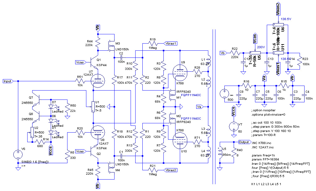
After the BHEL84 and my previous cascoded amp, I would like to build the amp in attachment inspired by this thread and others as well.
I would like to ask you how close it is needed to match the mosfets and BJTs in these amps, and what is needed to take particularly care of.
Thanks!
Roberto
Attachments
I compared the FQPF5P20 and the FQPF9P25 to the fet I normally use (FQP3P50) and while it doesn't have the isolated case it does have significantly more SOA margin over the other two and the capacitance stays low to ~15V, whereas the other two start rising steeply at ~20V.
FQP3P50 seem no more available at mouser. In the same price range I see these two:
https://www.mouser.it/datasheet/2/308/1/FQP2P40_D-2313879.pdf
https://www.mouser.it/datasheet/2/308/1/FQP4P40_D-2314130.pdf
What do you use nowadays?
Second Zintolo's question...
I am not sure I need huge voltage tolerance; I don't plan to try this at high levels of FB, which by my calculations leaves less than 200V needed. Say 10% FB, so for a 400V B+ I have bias g1-k voltage of ~35V, and 1/11*400V at idle. Add in another 1/11*400V for when the one side gets cut off and I am at a hair over 100V d-s.
Of course right now I have no power Iron that will give me 400V, but that is but a detail...LOL A UTC S44 when rigged with its 1050V CT should come close, and I am sure I can find another pair of S-37's to go with 'em.
cheers,
Douglas
All 300 something FQP3P50 that TME had few hours ago at a reasonable price, are gone.
I report here an interesting document concerning SOA for linear use of mosfets:
https://www.onsemi.com/pub/collateral/an-4161.pdf
I report here an interesting document concerning SOA for linear use of mosfets:
https://www.onsemi.com/pub/collateral/an-4161.pdf
- Home
- Amplifiers
- Tubes / Valves
- If UNSET and the RCA50W Had a Baby