Some 2-wire plugs have a wide spade, and a narrow spade.
The idea was that the narrow spade was Hot, and the wide spade was Neutral.
That worked fine, as long as All of the homes power outlets were wired Correctly.
But heaven help whoever uses a power outlet that is wired Incorrectly.
And, not all device power inputs are the same.
Many varied connections, parts, etc.
Always refer to an accurate schematic (or if no schematic is available, create your own accurate schematic).
Then determine what is safe, and what is non-safe, etc.
Again, test power outlets, test products, test the combination of the outlet versus the product, just to be safe!
Last edited:
Well, I completed the restore and it looks and sounds great. All of the coupling caps I replaced were really leaking and way out of spec, one was leaking 2amps at 400v and not going down, most increased current leakage during testing which should not be the case. A couple of the bypass caps would not even register as caps with my Sencore and my cheap tester. I also replaced a few resistors that were out of spec. I did use cans, sorry, I like to keep original as I can and they fit really nice and tested excellent. I mostly used orange drops for everything else. Yes, I even took out the time to unsolder pins to add the new components, I was going to do the old wrap around but I kinda knew I wouldn't before I started.
Still waiting delivery of safety caps.
Still waiting delivery of safety caps.
Do remove them ! The do noting good ( if you want a mains filter, get a proper one). The only thing these caps add is security risks ( fire, shock )
Get them out !
I was getting ready to use some and stumbled on this thread and thought "But they make ones specifically for the task, they must be better and safe now" And then I saw the attached warning on Kemet's site. So clearly there is still danger with them
Attachments
As I understand it, power conditioners use X and or Y type caps to filter noise out of the 60Hz source and use a MOV for surge protection. Is that the same thing we are talking about in this thread or is that something different? I also noticed that it seems to stiffen the AC voltage. The Furman line conditioner in my guitar amp rack is simply this.
Stiffen the AC voltage with a 0.1 uF capacitor? It does not stiffen the AC line voltage.
Neither does an MOV, it goes low Z only when the voltage exceeds the Mains Power normal voltage (like a high voltage transient).
Do a little math:
Suppose you have a mains power outlet that puts out 120V at 0 Amps (unloaded).
Suppose that same mains power outlet puts out 117V at 14 Amps, just below the breaker trip level.
120V -117V = 3V.
3V/14 Amps = 0.214 Ohms, the resistance of the house wiring, and the mains power outlet to the plug of the amplifier power cord.
A 0.1 uF capacitor at 60 Hz = 26.5k Ohms of capacitive reactance.
The same 0.1 uF capacitor at 20 kHz = 79.5 Ohms of capacitive reactance.
You are not going to stiffen the 0.214 Ohm resistance of the mains power by putting
a 26.5k Ohm, or even a 79.5 Ohm resistor in parallel with 0.214 Ohms.
OK, so try a 1 uF capacitor there. Even at 20 kHz, it is 7.95 Ohms, not much effect across a 0.214 Ohm resistance.
Conclusion:
If you did not understand the Safety Implications of the above, then see post # 28 (2 posts after this).
. . . The results can be shocking!
Last edited:
I was getting ready to use some and stumbled on this thread and thought "But they make ones specifically for the task, they must be better and safe now" And then I saw the attached warning on Kemet's site. So clearly there is still danger with them
The safest amp has none of these so called "safety capacitors" They do
no good when there and might cause harm. Why then install them ?
I agree with petertub,
Sorry, I did not make it obvious in my post # 26 why you should not do this.
It will Not reduce the noise.
It will endanger others.
Now, do NOT try another trick that has been done more than once, the purpose of doing it was to lower noise; but it can kill.
After it kills, the place becomes really quiet.
A 1uF cap from mains line 1, to another 1uF cap, and the other end of the 2nd 1uF cap to line 2. And the junction of the two capacitors to ground and the chassis.
At 60 Hz, the capacitive reactance of each cap is 2.65k Ohms. The Thevenin equivalent of the center of that is 1.325k Ohm. And that normally goes to power mains ground, and to the chassis.
Now, suppose the ground connection lifts, then the chassis is at 60V from a 1.325k Ohm source.
Do not grab the chassis if that happens!
"If anything can go wrong, it will" - Murphy
Just one more of the "Surviving Spouse Syndrome" stories.
Last edited:
Stiffen the AC voltage with a 0.1 uF capacitor? It does not stiffen the AC line voltage.
Neither does an MOV, it goes low Z only when the voltage exceeds the Mains Power normal voltage (like a high voltage transient).
Do a little math:
Suppose you have a mains power outlet that puts out 120V at 0 Amps (unloaded).
Suppose that same mains power outlet puts out 117V at 14 Amps, just below the breaker trip level.
120V -117V = 3V.
3V/14 Amps = 0.214 Ohms, the resistance of the house wiring, and the mains power outlet to the plug of the amplifier power cord.
A 0.1 uF capacitor at 60 Hz = 26.5k Ohms of capacitive reactance.
The same 0.1 uF capacitor at 20 kHz = 79.5 Ohms of capacitive reactance.
You are not going to stiffen the 0.214 Ohm resistance of the mains power by putting
a 26.5k Ohm, or even a 79.5 Ohm resistor in parallel with 0.214 Ohms.
OK, so try a 1 uF capacitor there. Even at 20 kHz, it is 7.95 Ohms, not much effect across a 0.214 Ohm resistance.
You are correct as always, but when I measured the voltage coming off the Transformer without the conditioner and then again with the conditioner, voltage had increased by a few volts. The only circuitry in the Furman conditioner is a XC and MOV. (seems like a rip off considering what they charge for it) so what is going on there if it is not a stiffening even if it's just a couple volts? Where is the extra volts coming from?
Based on your posts is the Furman conditioner a potential safety problem?
Last edited:
Any device connector to AC grid is a potential safety problem. EspeciallyYou are correct as always, but when I measured the voltage coming off the Transformer without the conditioner and then again with the conditioner, voltage had increased by a few volts. The only circuitry in the Furman conditioner is a XC and MOV. (seems like a rip off considering what they charge for it) so what is going on there if it is not a stiffening even if it's just a couple volts? Where is the extra volts coming from?
Based on your posts is the Furman conditioner a potential safety problem?
if external surfaces are not connected to ground. That is why 3 wire connectors
are used to enhance safety. It also an argument to disallow any connection
with any component between any of the grid lines and external surfaces.
I am not sure about your Furman conditioner. I do not have any real data on it.
Part of safety is how the Furman parts are connected, how your amplifier power in is wired, and how your power mains are wired.
Another part is the integrity of the ground, related to the mains power, all the house wiring, power cord(s), your amplifier, etc.
Mains Power almost always has harmonic distortion.
The 3rd harmonic is the Dominant distortion.
50 Hz power = 150 Hz 3rd harmonic. 60 Hz power = 180 Hz 3rd harmonic.
The third harmonic makes the sine wave look like it has mild clipping.
Mild clipping is a shortening of the voltage peaks.
But the Power Company charges you for the RMS power; not for the peak power, nor peak power voltage.
Locally, the power company is supposed to have 3% or less distortion.
But sometimes they have up to 5% distortion.
A really good line filter might reduce the 3rd harmonic.
If it can put any of that energy back into the fundamental (50 Hz or 60 Hz),
then there will be more Peak voltage.
B+ voltage amplitude generally relates to peak voltage, especially for a Cap input B+ filter.
True choke input filters (with at least the critical inductance), relates to the Average voltage.
On more issue:
In this world there are 3 types of AC Voltage meters:
1. Peak Voltage responding.
2. Average Voltage responding (average of absolute voltage amplitudes, not + and -, which averages to Zero).
3. True RMS Voltage responding.
The old VTVM and TVM were Peak responding.
The old VOM were Average responding.
Some of DMM are True RMS responding, others are not, but in that case they are generally Average responding.
Any company that produces a DMM that is True RMS responding, they tell you that because it is so useful, and they can and do charge you more for True RMS responding.
All 3 were calibrated by measuring a pure sine wave standard voltage source.
The peak responding meters sometimes only had peak scales, and sometimes also had RMS scales.
The fact is, if you measure a distorted sine wave (like mains power AC), you will get 3 different readings.
Take the distortion "out" first, and than all 3 will read the same number (well, a peak responding meter with only a peak scale, will read 1.414 times more than the others).
Which kind of AC meter do you have, Peak responding, Average responding, or True responding?
RF Power meters are another story.
"A man with one watch knows the time, a man with 2 watches is never sure" - Unknown
Last edited:
The depth of your knowledge on electric engineering is impressive. I have a Fluke 18B+ which I use for most things, I don't know which of the 3 types it is. If I get what your saying it sounds like the extra volts comes from the filtering of the the harmonics and putting that energy back into the source. Now I want to open it back up and take another look. I don't remember there being much of anything in there.
Testing everything is good advice but, as we all know, very few people do this. They just plug something in and expect it to work properly. And we have no idea who might be using the equipment in the future or under what circumstances.Some 2-wire plugs have a wide spade, and a narrow spade.
The idea was that the narrow spade was Hot, and the wide spade was Neutral.
That worked fine, as long as All of the homes power outlets were wired Correctly.
But heaven help whoever uses a power outlet that is wired Incorrectly.
Again, test power outlets, test products, test the combination of the outlet versus the product, just to be safe!
I speculated earlier that it might be advantageous to have both a 3 wire cord and a Y2 rated cap from neutral to ground due to the possibility that equipment may, at some point, be plugged into a circuit that is not wired properly.
For example, a 3 wire outlet in which the safety ground is not actually connected and the hot and neutral wires are switched (ie what should be hot is actually wired neutral and vice versa).
In that scenario, wouldn't having a Y2 cap on the neutral be safer than having no safety cap?
No. As you said you cannot trust the house wiring until it's examined. AndTesting everything is good advice but, as we all know, very few people do this. They just plug something in and expect it to work properly. And we have no idea who might be using the equipment in the future or under what circumstances.
I speculated earlier that it might be advantageous to have both a 3 wire cord and a Y2 rated cap from neutral to ground due to the possibility that equipment may, at some point, be plugged into a circuit that is not wired properly.
For example, a 3 wire outlet in which the safety ground is not actually connected and the hot and neutral wires are switched (ie what should be hot is actually wired neutral and vice versa).
In that scenario, wouldn't having a Y2 cap on the neutral be safer than having no safety cap?
a 3 wire outlet missing ground is an error and should be fixed.
Avoiding "safety caps" will reduce the risks in all circumstances, there is no place for them. Ever !
Checking the households cabling is a cheap and reliable way of increasing
safety.
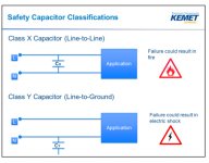
They're called "safety" X and Y capacitors since a safety agency has evaluated and approved their usage. When capacitors must be used on the AC line for suppression of radio frequency interference, they are they are the only types that will be approved by a safety agency.
When a 3-wire cord is used, there is likely no need for X or Y capacitors (though an X-capacitor might reduce the pop at turn-off). With a 2-wire cord, a Y-capacitor on the neutral may reduce hum caused by coupling through the transformer primary-to-secondary capacitance. It may increase hum if plug is reversed. In this case there will also be ground leakage current (YOU may be the ground conductor) which depends on the capacitor value. Safety agencies limit this to 0.7 mA or less, considered imperceptible in most cases. (1 mA is considered the "startle" threshold, not dangerous but could cause you to jump or drop something) A capacitor of .015 uF or less will meet this limit at 120VAC. Switching power supplies generally need Y-capacitors on both sides of the AC line, so the chassis may be "hot" at half line voltage with either plug polarity, but must meet a leakage current limit. If a 3-wire cord is used, the limit may be relaxed in some cases, since the ground leakage isn't a hazard unless the ground fails.
When a 3-wire cord is used, there is likely no need for X or Y capacitors (though an X-capacitor might reduce the pop at turn-off). With a 2-wire cord, a Y-capacitor on the neutral may reduce hum caused by coupling through the transformer primary-to-secondary capacitance. It may increase hum if plug is reversed. In this case there will also be ground leakage current (YOU may be the ground conductor) which depends on the capacitor value. Safety agencies limit this to 0.7 mA or less, considered imperceptible in most cases. (1 mA is considered the "startle" threshold, not dangerous but could cause you to jump or drop something) A capacitor of .015 uF or less will meet this limit at 120VAC. Switching power supplies generally need Y-capacitors on both sides of the AC line, so the chassis may be "hot" at half line voltage with either plug polarity, but must meet a leakage current limit. If a 3-wire cord is used, the limit may be relaxed in some cases, since the ground leakage isn't a hazard unless the ground fails.
Last edited:
I'm not asking about safety caps in general or the importance of having your house wired correctly.No. As you said you cannot trust the house wiring until it's examined. And a 3 wire outlet missing ground is an error and should be fixed.
Avoiding "safety caps" will reduce the risks in all circumstances, there is no place for them. Ever !
Checking the households cabling is a cheap and reliable way of increasing
safety.
My question only involves the specific situation I mentioned.
"A 3 wire outlet in which safety ground is not actually connected and the hot and neutral lines are switched (ie what should be hot is actually neutral and vice versa)."
So, in your opinion, in the specific situation I mentioned, no Y2 cap would be safer than having a Y2 on the neutral? Please explain why.
In this specific case you do not know if your "safety cap" will connect toI'm not asking about safety caps in general or the importance of having your house wired correctly.
My question only involves the specific situation I mentioned.
"A 3 wire outlet in which safety ground is not actually connected and the hot and neutral lines are switched (ie what should be hot is actually neutral and vice versa)."
So, in your opinion, in the specific situation I mentioned, no Y2 cap would be safer than having a Y2 on the neutral? Please explain why.
live or neutral. If it connects to neutral there is no hazard with or without
the so called "safety cap". But if it connects to live then a broken cap will
get voltage on the chassies a non existing cap is of no harm.
Thus the cap may be harmless but may also be dangerous . Of course
the cap must be broken to be dangerous but will you bet your life on
the cap's quality ?
- Status
- This old topic is closed. If you want to reopen this topic, contact a moderator using the "Report Post" button.
- Home
- Amplifiers
- Tubes / Valves
- Safety capacitors or not