Dear Members, after reading a lot about cheap NJ Fx Audio Tube 01 hence got one and upgrading the Caps and Tubes.
The result is 50% better sound stage than stock unit so its definitely a good pre and can be used as buffer too.
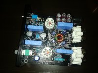
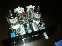
Upgraded film caps to Rifa with 2% tolerance, went with Rubycon or Nichicon 330uf caps and didnt touch the 470uf on Psu as they seemed okay.
Definitely change to a better 12v power supply than stock, GE5654 tubes and wow the bass and tube effect is worth enjoying.
The result is 50% better sound stage than stock unit so its definitely a good pre and can be used as buffer too.
Upgraded film caps to Rifa with 2% tolerance, went with Rubycon or Nichicon 330uf caps and didnt touch the 470uf on Psu as they seemed okay.
Definitely change to a better 12v power supply than stock, GE5654 tubes and wow the bass and tube effect is worth enjoying.
Attachments
I have just bought the same Model 01 with the Jan 5664 tubes. It's still in the burn-in phase, so hard to say what it will sound like, but even now it sounds pretty decent for the money.
The problem I have is that it has way too much gain. With my Cambridge Dacmagic 100 directly coupled to the input and the Model 01 feeding into my Harman Kardon PA2200 , I get really high volume after the third click of the volumepot, the first two clicks doing absolutely nothing.
Has anyone had a look at which resistors set the gain in this pre-amp?
Best regards.
Please show the schematics to us and most probably we may tell.
Best regards!
I wish I could. I've been scouring the Internet but schematics are virtually unobtanium. I can't locate them anywhere so I wondered if someone over here has had more luck.
Best regards.
There seem to be a few variations of this design, which is sold under a wide variety of brand names with slightly different features. These units are not buffers, they have gain, and most modern sources put out enough signal that a simple attenuator is all that's really necessary.I've been scouring the Internet but schematics are virtually unobtanium. I can't locate them anywhere so I wondered if someone over here has had more luck.
There is a mega-thread about these preamps over on the AK forum. Some posts on there include schematics.
There are at least two different power supply designs but, ultimately, the various brands seem to use the same operating points for the tubes. Those operating points are far from optimal.
I was in the process of breadboarding a very basic preamp and was trying a variety of tubes so I tried these tubes using the stock operating points. I used a traditional PS, however, so I was able to experiment. I found that they sounded much better when operated at higher voltages with different operating points. I posted about all this in the AK thread.
FX Audio 6j1 tube preamp - a $31 wonder | Page 66 | Audiokarma Home Audio Stereo Discussion Forums
There seem to be a few variations of this design, which is sold under a wide variety of brand names with slightly different features. These units are not buffers, they have gain, and most modern sources put out enough signal that a simple attenuator is all that's really necessary.
There is a mega-thread about these preamps over on the AK forum. Some posts on there include schematics.
There are at least two different power supply designs but, ultimately, the various brands seem to use the same operating points for the tubes. Those operating points are far from optimal.
I was in the process of breadboarding a very basic preamp and was trying a variety of tubes so I tried these tubes using the stock operating points. I used a traditional PS, however, so I was able to experiment. I found that they sounded much better when operated at higher voltages with different operating points. I posted about all this in the AK thread.
FX Audio 6j1 tube preamp - a $31 wonder | Page 66 | Audiokarma Home Audio Stereo Discussion Forums
Thanks, I'll have a look over there.
Best Regards.
Although MKT's might not be the best capacitors for audio use, I'd keep my hands off of Rifa's due to bad experience I've gathered during the last decades. They're prone to emulate firecrackers.
Better go for MKP's if there's enough space in your PCB.
Best regards!
Thanks for feedback, I was originally looking for WIMA 1uf Caps but couldnt lay my hands on them, these Rifa are measured to precision and time will tell. Moreover gain thing is pretty loud, using as Pre on a 80wpch ss power amp this baby doesnt even need to go above 8oclock.
I have just bought the same Model 01 with the Jan 5664 tubes. It's still in the burn-in phase, so hard to say what it will sound like, but even now it sounds pretty decent for the money.
The problem I have is that it has way too much gain. With my Cambridge Dacmagic 100 directly coupled to the input and the Model 01 feeding into my Harman Kardon PA2200 , I get really high volume after the third click of the volumepot, the first two clicks doing absolutely nothing.
Has anyone had a look at which resistors set the gain in this pre-amp?
Best regards.
You need to take a look at the Dacmagic and see what its output is before you set blame on the 01 unit. Does the 01 have gain or is it a straight buffer? I would suggest testing the units and if the 100 has too much output simply pad it down.
Tube (valve) Audio Buffers – FarMedia
An interesting article I came across:
FX Audio “TUBE-01”
In the TUBE-01 , the tube buffers are run at a low 25 Volt B+. This is an unusually low operational voltage (the tubes are spec’d at 120 Volts). As electronics tend to behave very differently on low voltages, this may explain why tube swaps are claimed to have such a large effect on the sound in these units.
The input goes directly to the volume control, which presents a 50K input load to the input. This is high enough to not be an issue.
No input cap, so DC on the input may cause scratchiness from the volume control.
From there, the circuit adds 12 dB of gain with no load, and about 10 dB with the usual 10K-20k load the following amp would present. This tells us the output stage is a less desirable high impedance design (probably off the tubes anode) and it will be affected by the the next device quite a bit. Signal level, low frequency response, and THD are likely to be worse.
First quick test results
Like the other unit, this one has a rather high amount of distortion (about 0.4% THD). It rolls off the high end a bit and the low ends a lot, even into an unrealistically easy 100K load. This is very similar to the other unit.
Rather than do a full suite of measurements that merely illustrate how poorly this one measures, I immediately replaced the tubes and upgraded the smallish 1.0 uF output coupling cap to 4.7 uF parts.
Here’s what these two simple changes did. [author note: better photo!]
FX Audio Tube-01 with new tubes and larger output coupling caps.
This is a big improvement. THD about halved and the low frequency rolloff is less than 1 dB at 20Hz. These mods are quite worthwhile.
Author notes to self, remember to touch on:
Output topology and impedance loading – 100K vs 20K vs 10K?
Measurements -10 and -20dBV – (in process)
Does THD decrease over time. (ie long warmup?)
Check spectrum of THD (mostly “musical” 2nd?).
Tube swapping results – (NOS 5654W is better than the supplied tubes, done)
Rolled off bass response – output coupling capacitor too small? – (yes, 4.7uF looks about right for the TUBE-01).
Hi,
Fully agree with the guy from FarMedia. I am running the tubes at 12 V AC /just a trafo in front and directly to the heaters/. Took out the big resistor and the cap. Should be better if you have 6.3 V separately to both tubes - just a recon, will try.
Please share your experience.
Regards
Fully agree with the guy from FarMedia. I am running the tubes at 12 V AC /just a trafo in front and directly to the heaters/. Took out the big resistor and the cap. Should be better if you have 6.3 V separately to both tubes - just a recon, will try.
Please share your experience.
Regards
Hi, I'm doing some tests with a 2x 6j1p buffer called Tube-01.
I changed the in-out caps with quality panasonic MKPs, 3.3uF / 400v.
I replaced all the electrolytic caps on the power supply with panasonic 25V.
I replaced all the electrolytic caps on the anode with 50v nichicon and panasonic.
I have built an adjustable linear power supply that goes up to 22v.
I did some tests and by increasing the input voltage I can get up to + - 40 / 45v which is equivalent to an anode of 80 / 90v instead of the original 60v.
I was wondering if you know a working point that can work with 80 / 90v.
I presume I will have to replace the Rs on the anode and cathode and maybe some more.
For heaters I always keep exactly 6.3v (12.6v because they are in series) ... by means of a resistor.
Thanks if you give me a point (polarization) of work so I can apply it and see how it goes and make some measurements, as well as listening.
I also made some measurements with FFT ... original version .. and it distorts a lot!
I think that at 80 / 90v of anodic you can have a better result than at 60v.
Thanks!
")


When I commented earlier in the thread, I mentioned that I had breadboarded the FX in both stock form and using more "normal" operating points. It did sound much better when operated at normal voltages.Hi, I'm doing some tests with a 2x 6j1p buffer called Tube-01.
I changed the in-out caps with quality panasonic MKPs, 3.3uF / 400v.
I replaced all the electrolytic caps on the power supply with panasonic 25V.
I replaced all the electrolytic caps on the anode with 50v nichicon and panasonic.
I have built an adjustable linear power supply that goes up to 22v.
I did some tests and by increasing the input voltage I can get up to + - 40 / 45v which is equivalent to an anode of 80 / 90v instead of the original 60v.
I was wondering if you know a working point that can work with 80 / 90v.
I presume I will have to replace the Rs on the anode and cathode and maybe some more.
For heaters I always keep exactly 6.3v (12.6v because they are in series) ... by means of a resistor.
Thanks if you give me a point (polarization) of work so I can apply it and see how it goes and make some measurements, as well as listening.
I also made some measurements with FFT ... original version .. and it distorts a lot!
I think that at 80 / 90v of anodic you can have a better result than at 60v.
Thanks!
I'm amazed that people put so much effort into upgrades (tube rolling, caps, op amps etc) to the stock unit yet they ignore the sub-optimal operating point.
The problem with modifying the stock unit to produce those voltages is that so much needs to be changed to do it, including a different power supply. It sounds like you are addressing those issues - making sure that the voltage rating of the caps is high enough and that the heater voltage isn't too high.
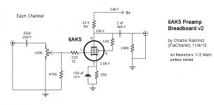
Anyway, I've attached the schematic of what I breadboarded, which was a big improvement over the stock operating points. I used a bench (traditional linear) power supply with some added filtration.
I'd be more inclined to just build something from scratch rather than modify the stock unit. I admit that's partly because I favor point to point wiring. And, if you build from scratch, why not try some other tube types. I probably tried at least 10 or 12 different types and, IMO, several others sounded better than the 6AK5. But modifying the stock unit doesn't give you much choice, just different variations of the same basic tube.
Also, I still see a lot of people refer to these as a "buffer". It is not, it's a simple anode follower design and with the 6AK5 the output impedance is not well suited for use with SS or Class D amps, which seem to be what most people are using them with. Their output impedance is fine for use with a tube amp but if you use a SS or Class D you will get better results by adding a cathode follower (buffer).
The other issue with the FX is the excessive gain. Not that this only applies to the FX, most all commercial preamps have this problem. The mu (amplification factor) of the 6AK5 in triode (as the FX uses it) is roughly 35.
Gain isn't really needed at all in most cases. Pretty much all amps can be driven to full power using a "passive preamp" (aka a simple volume control) if you use a modern source like a CD player or DAC. Even with zero gain, the signal usually needs to be attenuated. So, with a mu ~35, many people find it difficult to make minor level adjustments, it's either too loud or not loud enough because the range of the volume control is so limited.
In the end, the preamp I built uses the 1626 but I also liked the 6V7G and the Russian 2P29L better than the 6AK5. The 1626 has a mu of 5, so there's a bit of gain available if you ever need it. I mostly use tube amps but I also wanted to be able to drive my Yamaha SS power amp that has an input impedance of 20k. Ideally, that requires the preamp to have an output impedance of 2k or less. Because of the low plate resistance of the 1626, my pre has an output impedance of ~1.4k without using a cathode follower. Here's a thread about it:
1626 Preamp Build | Audiokarma Home Audio Stereo Discussion Forums
Attachments
Last edited:
Thanks for the answer.
Every word you say I share!
I know that it is a follower anode and that it also comes out with turned phase.
So that its gain is useless,
I don't need it.
I was also thinking of doing modification and exiting the cathode so that it is a real buffer. unfortunately the maximum anode voltage that I can reach is 80 / 90v.
I'm not going to do a buffer all over again.
i have this and i wanted to do something with this.
I made the various changes but I know very well that the working point is basic and most important of all.
I measured this "fake buffer", I saw the harmonics!
i thought 90 volts of anodic is better than 60v.
i just don't know the R values to use for a good working point.
unfortunately I only have 90v..nn more.
hindsight I would do one again but that would not even remotely resemble the tube-01. I would use other types of valves!
anyway thanks!
I'm a big believer in using the right tool for the job.Thanks for the answer.
Every word you say I share!
I know that it is a follower anode and that it also comes out with turned phase.
So that its gain is useless,
I don't need it.
I was also thinking of doing modification and exiting the cathode so that it is a real buffer. unfortunately the maximum anode voltage that I can reach is 80 / 90v.
I'm not going to do a buffer all over again.
i have this and i wanted to do something with this.
I made the various changes but I know very well that the working point is basic and most important of all.
I measured this "fake buffer", I saw the harmonics!
i thought 90 volts of anodic is better than 60v.
i just don't know the R values to use for a good working point.
unfortunately I only have 90v..nn more.
hindsight I would do one again but that would not even remotely resemble the tube-01. I would use other types of valves!
anyway thanks!
If you don't need gain and you do need something with low output impedance, then the FX is the wrong tool for the job. It offers exactly the opposite of what you need.
If you have the skills to mod the FX why not just build a buffer. A buffer has zero gain and it can drive a SS or Class D amp or long interconnect cables.
Here's a cheap kit that actually is a buffer.
Diy 6N3 Tube Buffer Bile Pre-amplifier Board For Filtering Amplifier Audio | eBay
This highly respected designer also offers buffer kits, and other things too. One is even powered by a 12v wall wart just like the stock FX.
Tube-Based Buffers
Here's a very detailed link about a DIY buffer build. The guy also posts on this forum and I'm sure he would be helpful if you have questions.
Muchedumbre Buffer Preamp – wauwatosa tube factory
Last edited:
- Home
- Amplifiers
- Tubes / Valves
- FX Audio Tube 01 Mods