G'day Guys,
I've been working through this one for a while now and I have nailed down enough of the design details to do a board layout.
Firstly a bit of background as this is not my first rodeo with the Aikido.
My first was a Tubes4hifi.com SP14 kit which I have absolutely loved the sound of since it first fired up something like a decade ago.
http://www.tubes4hifi.com/SP14.htm
I've also built one using Broskie's 12vac Aikido pcb.
New Aikido 12Vac PCB and part kits
I built the 18vac version using 12AU7 tubes. This is testing in my system. It's an amazingly elegant solution with a great sound but it was made for another project.
This brings us back to the SP14.
I chose to use a custom chassis instead of the stock one and this has created quite a headache. I simply cannot make the 254mm x 150mm pcb fit properly into my chassis without fouling on some other component.
It has been upgraded and rebuilt several times over the years but I've never been satisfied with the chassis layout.
Last time the SP14 ended up on my healing bench I decided I was sick of battling the blasted thing. It was time for a new solution. Time to salvage the components and find some new boards that fit.
I spent a lot of time looking at Broskies Mono Aikido board
Aikido Octal Dual-Mono PCB
But after much mocking up I discovered that it is just a weeny bit too large to work in my chassis. I also don't like where his ins and outs are located.
Thus I came to the point where I have to make my own boards.
Now, the design outline:
1) Mono board for maximum flexibility in chassis layout.
2) Within 100x100mm to take advantage of the JLCpcb special.
3) Separate PSU for maximum flexibility in chassis layout, also the JLCpcb thing.
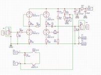
4) A textbook 6SN7 aikido like the old SP14
5) At least 50mm spacing for coupling caps for flexibility. I've always wanted to try some NOS Soviet caps but they never fit.
6) 12v heater supply to take advantage of Eba with a series/parallel selector switch so that I might try 12SN7s
7) Signal I/O and PSU I/O on opposite sides of the board for chassis layout purposes.
8) Fastons for PSU connections, Screw terminals for signal connections.
So here is what I have come up with so far.


I've separated the signal ground from the onboard decoupling.
I managed to get 58mm between the widest pads on the decoupling caps.
May I please ask for some feedback?
Does it pass muster?
Does anybody see any flaws?
Any suggestions for where things could be done better?
Insults are fine as long as they are witty.
I've been working through this one for a while now and I have nailed down enough of the design details to do a board layout.
Firstly a bit of background as this is not my first rodeo with the Aikido.
My first was a Tubes4hifi.com SP14 kit which I have absolutely loved the sound of since it first fired up something like a decade ago.
http://www.tubes4hifi.com/SP14.htm
I've also built one using Broskie's 12vac Aikido pcb.
New Aikido 12Vac PCB and part kits
I built the 18vac version using 12AU7 tubes. This is testing in my system. It's an amazingly elegant solution with a great sound but it was made for another project.
This brings us back to the SP14.
I chose to use a custom chassis instead of the stock one and this has created quite a headache. I simply cannot make the 254mm x 150mm pcb fit properly into my chassis without fouling on some other component.
It has been upgraded and rebuilt several times over the years but I've never been satisfied with the chassis layout.
Last time the SP14 ended up on my healing bench I decided I was sick of battling the blasted thing. It was time for a new solution. Time to salvage the components and find some new boards that fit.
I spent a lot of time looking at Broskies Mono Aikido board
Aikido Octal Dual-Mono PCB
But after much mocking up I discovered that it is just a weeny bit too large to work in my chassis. I also don't like where his ins and outs are located.
Thus I came to the point where I have to make my own boards.
Now, the design outline:
1) Mono board for maximum flexibility in chassis layout.
2) Within 100x100mm to take advantage of the JLCpcb special.
3) Separate PSU for maximum flexibility in chassis layout, also the JLCpcb thing.
4) A textbook 6SN7 aikido like the old SP14
5) At least 50mm spacing for coupling caps for flexibility. I've always wanted to try some NOS Soviet caps but they never fit.
6) 12v heater supply to take advantage of Eba with a series/parallel selector switch so that I might try 12SN7s
7) Signal I/O and PSU I/O on opposite sides of the board for chassis layout purposes.
8) Fastons for PSU connections, Screw terminals for signal connections.
So here is what I have come up with so far.
I've separated the signal ground from the onboard decoupling.
I managed to get 58mm between the widest pads on the decoupling caps.
May I please ask for some feedback?
Does it pass muster?
Does anybody see any flaws?
Any suggestions for where things could be done better?
Insults are fine as long as they are witty.
Last edited:
Just a comment since I like the simplest possible solutions.
Since both tubes have the same heater requirements, why complicate the board with a mechanism to change from parallel to serial? The heater supply can be set externally, and in the case of 6.3/12.6V, it could be an option to link the heater terminals of the boards in serial (12v supply, 6v each board) or in parallel.
Since both tubes have the same heater requirements, why complicate the board with a mechanism to change from parallel to serial? The heater supply can be set externally, and in the case of 6.3/12.6V, it could be an option to link the heater terminals of the boards in serial (12v supply, 6v each board) or in parallel.
I could be mistaken but I've never found any 12SN7's that were superior to 6SN7's. I personally see no need to switch from 6 volt to 12 volt. Just another gimmick. 6SN7's sound best when run around 250-300 volts on the plate. At 250 on the plate you can run some rather nice 5692's or some of the high dollar Russian military 6sn7 copies.
I use elevated DC heaters. On my 6SN7/6sn7 Aikido somewhere around 35-40 volts B+. I have no noise what so ever.
I think John uses up to 1/4 of the B+.
I use elevated DC heaters. On my 6SN7/6sn7 Aikido somewhere around 35-40 volts B+. I have no noise what so ever.
I think John uses up to 1/4 of the B+.
Last edited:
Thanks for the feedback guys.
I will have to have more of a think about what I am doing and why I am doing it.
For example: Buy online and sell with NZ's #1 auction & classifieds site | Trade Me is our local equivalent of Ebay in New Zealand and I have yet to see any 12SN7's come up for sale over many years. That is to say I am seriously reconsidering the need for the series/parallel switch. This would also decrease the width of the pcb about 10mm.
I am beginning to think that I might be better to go with a 6.3v heater and a super low dropout regulator like an LT3080.
The B+ will be 250v at the plate.
I have been planing to float the heaters 1/4 B+ as per Broskie.
One question I have been circling around is 'where' to locate the heater float.
Is this best done closer to the tubes themselves (eg on the signal board) or best done closer to the output of the B+ supply (eg on the B+ supply board)
[I am beginning to think that I might be better to go with a 6.3v heater and a super low dropout regulator like an LT3080.]
What is that going to do for you? Don't think you need it. I've built probably 1/2 dozen or more Aikido's since John brought them out and never resorted to using one. I think in most cases the KISS principle should be used. The simpler the better.
What is that going to do for you? Don't think you need it. I've built probably 1/2 dozen or more Aikido's since John brought them out and never resorted to using one. I think in most cases the KISS principle should be used. The simpler the better.
Member
Joined 2009
Paid Member
Heaters are high current, use max width traces.
Does R10 want to be an adjustable pot for best nulling of power supply noise ?
Do you want a cap to decouple the heater supply to ground ?
Could it be a good idea to have an additional pcb mounting support close to the valve bases where there is flexing stress during insertion and removal of the valves ?
Last edited:
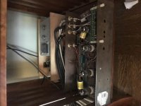
Let's go back to the original premise. You are rebuilding the pre-amp so that it fits into a chassis, not just rebuilding or building a new chassis? That just seems backwards. I get that the build is part of the fun of this hobby, but I'd look to build something completely new. The chassis for my Aikido, based on Broskie's original board, is a piece of Home Depot sheet steel bent into a U shape, with a separate 24v power supply based on a pre-built linear supply. I've been using it this way for 10 years now. 3 inputs, one output, and a remote controlled volume and selector, so no knobs or switches.
It is as dirty as it looks in the pic!
It is as dirty as it looks in the pic!
Attachments
Last edited:
Good Morning folks (here at least),
If I may summarise the feedback so far.
1)12.6v heater over 6.3v for simplicity which makes sense to me. Current demands was one reason I started with the 12.6v idea.
2) DC heaters are unnecessary with an aikido due to the circuits inherent high PSRR.
This one I struggle with as my first couple of tube preamps all had regulated DC heaters. My mind wants to view an AC heater as a backwards step.
Can anybody suggest any high quality resources for my consumption regarding AC vs DC heaters?
I have attempted to research around as I have seen it implied across various threads that DC heaters have some not so obvious draw backs. However, I cannot find a quality discussion on the matter. I seem to only find either AC = good or DC = good but no decent comparisons.
If I was to try and boil down the argument in this context, would it be something like?
"A properly implemented aikido receives no additional benefit from the added cost and complexity of a regulated DC heater."
For example, lets say I spent $20 making a pair regulated heater supplies.
If I am understanding correctly, this $20 would be best spent somewhere else eg: nicer tubes or a higher quality volume pot.
Last edited:
Let's go back to the original premise. You are rebuilding the pre-amp so that it fits into a chassis, not just rebuilding or building a new chassis? That just seems backwards. I get that the build is part of the fun of this hobby, but I'd look to build something completely new. The chassis for my Aikido, based on Broskie's original board, is a piece of Home Depot sheet steel bent into a U shape, with a separate 24v power supply based on a pre-built linear supply. I've been using it this way for 10 years now. 3 inputs, one output, and a remote controlled volume and selector, so no knobs or switches.
It is as dirty as it looks in the pic!
What I am trying to make here is a flagship piece for the living room system.
I want something that looks like fine artwork and sounds even better.
I have in fact done the very thing you suggest here:
I purchased a sheet of ali from Bunnings (NZ equivalent of home depot, It even has Rigid brand power tools but they are sold as AEG in this part of the world) bent it into a 'U' shape and whacked on some I/O bits. Voila!

Not very spill proof but a great test rig.
Version 2.0
Hi Guys,
Here is my version 2.0.


1)I removed the silly heater voltage selector switch.
2)Traces for the heater rails were increased to 5mm.
3)A heater float was added.
4)Width increased a bit to fit the new heater layout.
Anybody see anything problematic, stupid or braindead?
Any layout critiques?
Hi Guys,
Here is my version 2.0.
1)I removed the silly heater voltage selector switch.
2)Traces for the heater rails were increased to 5mm.
3)A heater float was added.
4)Width increased a bit to fit the new heater layout.
Anybody see anything problematic, stupid or braindead?
Any layout critiques?
Hi All,
In one of my designs (not yet built), i used SMD resistors for the grid stoppers.
I chose size 1206, so i can see them and manipulate them with tweezers.
And i placed them on the bottom side of PCB, as close as possible to the socket pin.
My 2 cents.
Best regards,
Serge
In one of my designs (not yet built), i used SMD resistors for the grid stoppers.
I chose size 1206, so i can see them
and manipulate them with tweezers.And i placed them on the bottom side of PCB, as close as possible to the socket pin.
My 2 cents.
Best regards,
Serge


Hi Sadface,
Did you ever get your PC boards fabricated? I would like to build and octal Aikido for a friend as he likes mine. I have an older version of the Glassware board, but all boards have been unavailable for quite a while. If you had your boards fabbed, would you be willing to share the Gerber files?
Thank you,
John
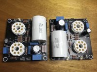
Hi John,
I've had the boards fabbed but they are as yet untested pending the completion of power supplies.
Progress is much slower than it used to be due to a beautiful baby girl.
I'm happy to share the gerbers, I should be able to get to my computer this evening. I've got a BOM spreadsheet somewhere too.
I've had the boards fabbed but they are as yet untested pending the completion of power supplies.
Progress is much slower than it used to be due to a beautiful baby girl.
I'm happy to share the gerbers, I should be able to get to my computer this evening. I've got a BOM spreadsheet somewhere too.
Attachments
- Home
- Amplifiers
- Tubes / Valves
- Home Brewed Aikido Preamp