A long overdue progress update.
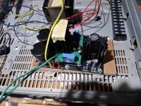
I went with the Jan Didden TReg for my b+ supply.
I made a motherboard to accommodate the raw b+, the TReg board and the heater regulator section.
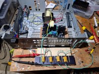
Having acquired a variac. I finally got to testing the power supplies over the last couple of evenings.


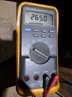
After trimming, the b+ is rock solid on 265vdc. The heaters are rock solid at 12.7vdc. No excessive heat from the heatsinks under load.
Not quite ideal on the heater voltage but I don't think 0.7% out is much to worry about. IIRC, datasheets typically specify +/-10%.
I also found an error on the silkscreen/bom. The resistor values used were the values that Broskie recommends for a headphone amp. So I changed the 4 or so resistors on each board to the slightly more optimal values for a lifestage. I don't think the difference would have been noticeable. But I had the resistors on hand so I figured why not?
Now that the power supply boards are tested and working. I can finally rig up a proper test of the smp boards.
It will probably take me a couple of weeks. I will rig up a basic setup in a scrap chassis and commence the next round of testing.
I went with the Jan Didden TReg for my b+ supply.
I made a motherboard to accommodate the raw b+, the TReg board and the heater regulator section.
Having acquired a variac. I finally got to testing the power supplies over the last couple of evenings.


After trimming, the b+ is rock solid on 265vdc. The heaters are rock solid at 12.7vdc. No excessive heat from the heatsinks under load.
Not quite ideal on the heater voltage but I don't think 0.7% out is much to worry about. IIRC, datasheets typically specify +/-10%.
I also found an error on the silkscreen/bom. The resistor values used were the values that Broskie recommends for a headphone amp. So I changed the 4 or so resistors on each board to the slightly more optimal values for a lifestage. I don't think the difference would have been noticeable. But I had the resistors on hand so I figured why not?
Now that the power supply boards are tested and working. I can finally rig up a proper test of the smp boards.
It will probably take me a couple of weeks. I will rig up a basic setup in a scrap chassis and commence the next round of testing.
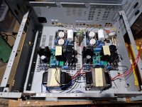
Here's a mockup of what I'm going to do.
My test chassis will be an old Harman kardon receiver chassis because it's convenient and big enough.

A bit of metal working to cut a hole for the IEC socket and power switch.
Otherwise I just need to drill a bunch of mounting holes.
Volume pot and source selection will be on shift extensions.
Whack in a few rca sockets and then it's just wiring.
My test chassis will be an old Harman kardon receiver chassis because it's convenient and big enough.

A bit of metal working to cut a hole for the IEC socket and power switch.
Otherwise I just need to drill a bunch of mounting holes.
Volume pot and source selection will be on shift extensions.
Whack in a few rca sockets and then it's just wiring.
Everyone should have a pal like Grover. 😉I just used a pair of your boards to build a 6SN7 Aikido for a pal. Worked out very well. I stuck the caps on the underside and mounted the socket side flush with the top plate. 5Y3 rectifier, one film cap, Neurochrome 20th Century Maida board for the B+, and one of v4lve lover's 6V in > 6V out boards for the filaments (with a bit of creative wiring). Khozmo attenuators. Glassware selector switch. VERY quiet. ;-)
One thing I did was to drill a very small guide hole in the center of the each octal space on the board, in order to create an easy template for drilling the socket holes in the top plate.
View attachment 1359928