This is a thread about parafeed headphone tube amps. It's open for anyone and everyone to join in and add their experiences, experiments, tips and traps. The more the better! I hope for plenty of variety and contributers.
I have AKG K701 headphones, 62 ohms, and have long been curious about a tube amp to drive them. So finally I started putting a few designs together.
Version 1
This used a 6N30 with just a LL1660/18 interstage in 4.5:1. Might have worked into 300R cans but no good for 62R. Needs more step-down. So on to parafeed.
Version 2
Cunning plan was to use a mains transformer 60VA 230/12+12 as OPT giving 9.6:1 step-down. Kept the 6N30 and LL1660/18 as a plate choke with FT-2 0.2uF coupling cap. Cap size could be bigger so will look at that later. This was now well inside the ballpark and sounded generally very promising. I had help from Shoog and others regarding mains transformers. Tried damping the output with a 120R resistor but preferred without. Good tip is to reverse the primaries and use the preferred wiring, and this did make an audible difference. The 60VA size may be unnecessarily large but I just slightly preferred it to a 25VA I tried. Others have used sizes down to 5VA.
Version 3
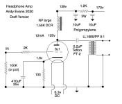
Plan here was to use the best parts I have, which are a NP Acoustics 40mA amorphous plate choke and a LL1689 OPT in 9:1. This was now better then V2. Sound was fuller and more detailed. Tube was a 6J1P with Rp of 4.7K. A bit high maybe so next step is to try other tubes with the same iron. I have plenty of volume with my DAC outputting 2v, so the 4P1L and 2P29L look like the next ones to try. On to directly heated tubes, so hoping for more clarity/timbre. These will be tried in SIC diode bias and filament bias.
I have AKG K701 headphones, 62 ohms, and have long been curious about a tube amp to drive them. So finally I started putting a few designs together.
Version 1
This used a 6N30 with just a LL1660/18 interstage in 4.5:1. Might have worked into 300R cans but no good for 62R. Needs more step-down. So on to parafeed.
Version 2
Cunning plan was to use a mains transformer 60VA 230/12+12 as OPT giving 9.6:1 step-down. Kept the 6N30 and LL1660/18 as a plate choke with FT-2 0.2uF coupling cap. Cap size could be bigger so will look at that later. This was now well inside the ballpark and sounded generally very promising. I had help from Shoog and others regarding mains transformers. Tried damping the output with a 120R resistor but preferred without. Good tip is to reverse the primaries and use the preferred wiring, and this did make an audible difference. The 60VA size may be unnecessarily large but I just slightly preferred it to a 25VA I tried. Others have used sizes down to 5VA.
Version 3
Plan here was to use the best parts I have, which are a NP Acoustics 40mA amorphous plate choke and a LL1689 OPT in 9:1. This was now better then V2. Sound was fuller and more detailed. Tube was a 6J1P with Rp of 4.7K. A bit high maybe so next step is to try other tubes with the same iron. I have plenty of volume with my DAC outputting 2v, so the 4P1L and 2P29L look like the next ones to try. On to directly heated tubes, so hoping for more clarity/timbre. These will be tried in SIC diode bias and filament bias.
Attachments
Last edited:
Good to see some progress with your experimentation.
I have to admit I know little about 6J1, but the are plenty of recommendations/designs for 2P29L and 4P1L, which may well suit a 32 to 60 Ohm load better. I dont really know...
I have been on a similar path, except that I have been designing for a 300R load - somewhat easier I guess.
My experiments with mains transformers have worked OK the latest using very small VA toroid particularly so.
I have tried to drive 32R with a larger ratio transformer and was disappointed.
I am using DH Russians too, 1J24B, 1J29B; and I have 1P24B in reserve for heavy loads like 32R. Maybe that's overkill?
My circuit drives perhaps 25V RMS into the primary, relatively small signal swing, making something like Edcore XSM series OK. Larger swings would approach the max voltage before core saturation in that range of line transformers.
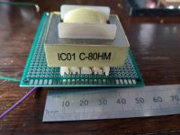
However, I have bought some transformers from ebay, which may allow me to drive down to 32R a lot better.
These are 100V line transformers, with a 2k:8R ratio, which would give about 8k:32R.
Photo attached.
I'm not sure what reflected load you are looking for (must go and read the other thread)
Following with interest")
I have to admit I know little about 6J1, but the are plenty of recommendations/designs for 2P29L and 4P1L, which may well suit a 32 to 60 Ohm load better. I dont really know...
I have been on a similar path, except that I have been designing for a 300R load - somewhat easier I guess.
My experiments with mains transformers have worked OK the latest using very small VA toroid particularly so.
I have tried to drive 32R with a larger ratio transformer and was disappointed.
I am using DH Russians too, 1J24B, 1J29B; and I have 1P24B in reserve for heavy loads like 32R. Maybe that's overkill?
My circuit drives perhaps 25V RMS into the primary, relatively small signal swing, making something like Edcore XSM series OK. Larger swings would approach the max voltage before core saturation in that range of line transformers.
However, I have bought some transformers from ebay, which may allow me to drive down to 32R a lot better.
These are 100V line transformers, with a 2k:8R ratio, which would give about 8k:32R.
Photo attached.
I'm not sure what reflected load you are looking for (must go and read the other thread)
Following with interest
Attachments
Last edited:
Hi Shoog! Indeed. I have some of Ale's Gyrators, so that's going to be a future build. I'm trying to go through all the options, since headphone amps are new to me. Time consuming, and I'm well aware that all the obvious solutions have already been tried out. There are some good published circuits, and Ale has been very helpful here as always. Plus your experiments with mains transformers have been really insightful.
Also something to think about, a high rp valve is going to really struggle to drive the parasitics of any transformer - especially a mains transformer. The result will be a dull sound or excessive ringing which I think is what your experiments are showing.
A beefy low rp valve will give the best results, ideal candidates would be E55L (triode strapped), ECC99, 5687, ECF80 (with the triode loaded with the pentode as a CCS), or a great simple little spud can be made with a ECL82.
Shoog
A beefy low rp valve will give the best results, ideal candidates would be E55L (triode strapped), ECC99, 5687, ECF80 (with the triode loaded with the pentode as a CCS), or a great simple little spud can be made with a ECL82.
Shoog
Last edited:
Rp is a good point, but doesn't that come with caveats?
For example, in my tiny headphone amp, I thought a high Rp was an issue with some toroid I was using at the time, 30VA.
But in my output stage, I have used quite a large amount of plate to grid local feedback; Rf of 220k to Ri of 22k, lowering output impedance.
So I'd tentatively say output impedance and use of/lack of feedback has a huge impact.
Andy,
Out of interest, have you tried finding output impedance by experimentation?
If I recall, I measured maximum output voltage across my 330R load, then changed the load to 300R, then 390R and measured again.
Finding the change in V, and with the change in R known, the change in I can be found.
Then dV/dI gives output impedance referred to secondary winding.
In my case with 300R load, output resistance was about 180R.
Referring back to primary side, multiplying by the impedance ratio gave about 7k or 8k output impedance, or source impedance seen by the OPT.
from memory, which is always risky for me!
Last edited:
Looking forward to this thread!
I designed a parafeed headphone amp a while ago. The starting point was the "Tucker" design with a direct coupled 45 tube. I took various ideas and thoughts and added them to the design (CCS, active loads and stuff). I have to admit that I never really got around to build it, although I have most of the parts... the latest version of the design is here: 45 amp build direct coupled (post 116)
Oh, and I do agree that solid-state CCS/gyrators tend to work closer to the theoretical ideal of an inductor than many real-world inductors. However, CCS/gyrators require a substantial DC drop. This means that the B+ must be (a lot) higher. This is why I used a normal inductor as the load for the output tube in my design.
Great to see your designs mbrennwa. Why did you figure you needed two stages when you are using an OPT? 2 stages are usually designs with no OPT. I'm assuming that one stage can do this.
Currently making a 4P1L stage on the bench and hope to have it ready today. I'm at home all the time so I can hopefully make quick progress. I use a modular system with various top plates that fit together, so I have all the components ready to mix and match. It's my alternative to breadboarding.
Currently making a 4P1L stage on the bench and hope to have it ready today. I'm at home all the time so I can hopefully make quick progress. I use a modular system with various top plates that fit together, so I have all the components ready to mix and match. It's my alternative to breadboarding.
All transformers have parasitics which produce peaking. When you buy a high end transformer, such as a 10K:300r, those parasitics will have been optimized to produce a flat response at the specific valve rp (10K) and the specific load (300R). If you diverge from that scenario you will see frequency anomalies caused by load mismatch. In the case of Lundahl they specify snubber arrangements to flatten the response for the specific arrangement the transformer is sold for. This application specific optimization becomes increasingly important the higher the rp of the valve they are targeted at.
This is the reason why loading down the secondary will tend to damp the parasitics and hence flatten the response. When using power transformers none of this has been considered so the only way to get them to perform well is to swamp the parasitics by driving them hard with a low rp valve and loading them heavily with a fixed low impedance load. Anything else is pure luck if it sounds well.
Shoog
Hi Shoog. To keep it simple a low Rp valve is certainly what we should be aiming for - trying to stay under 3K which does give some likely suspects. I take your point about correct loading. I'll have to look at this in future builds. Luck is always welcome, though hard to design for!
Shoog,
I am not disagreeing with your points, merely a little perplexed by my testing results, which don't seem to agree.
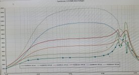
I have tested a 'nice' SE OPT, using 10k source impedance, and my impedance curve data is the opposite of what you have stated, or my interpretation is flawed.
The OPTs were loaded with their intended secondary load, result: huge ultrasonic resonance peaks, 2 or more.
Increasing the load R, doubling each step, and the resonance is damped more and more, until at 4 times the secondary load, the bandwidth is reduced.
Of course this may be an artifact of the particular OPT (Jan Western Atra0288), and besides I didn't test using half normal secondary load - which would increase bandwidth, and also severity of the resonances.
Nor have I ventured to try a snubber across the primary...
I am not disagreeing with your points, merely a little perplexed by my testing results, which don't seem to agree.
I have tested a 'nice' SE OPT, using 10k source impedance, and my impedance curve data is the opposite of what you have stated, or my interpretation is flawed.
The OPTs were loaded with their intended secondary load, result: huge ultrasonic resonance peaks, 2 or more.
Increasing the load R, doubling each step, and the resonance is damped more and more, until at 4 times the secondary load, the bandwidth is reduced.
Of course this may be an artifact of the particular OPT (Jan Western Atra0288), and besides I didn't test using half normal secondary load - which would increase bandwidth, and also severity of the resonances.
Nor have I ventured to try a snubber across the primary...
Attachments
Last edited:
Shoog,
I am not disagreeing with your points, merely a little perplexed by my testing results, which don't seem to agree. The main difference between a power toroidal and a EI OPT is the type of parasitics. In a power toroidal the parasitics are almost exclusively capacitive, but in a EI OPT there is significant leakage inductance as well.
I have tested a 'nice' SE OPT, using 10k source impedance, and my impedance curve data is the opposite of what you have stated, or my interpretation is flawed.
The OPTs were loaded with their intended secondary load, result: huge ultrasonic resonance peaks, 2 or more.
Increasing the load R, doubling each step, and the resonance is damped more and more, until at 4 times the secondary load, the bandwidth is reduced.
Of course this may be an artifact of the particular OPT (Jan Western Atra0288), and besides I didn't test using half normal secondary load - which would increase bandwidth, and also severity of the resonances.
Nor have I ventured to try a snubber across the primary...
These things are always going to be unique to the particular transformer so your results make perfect sense in that context.
I have just personally experienced best result with toroidals when the rp is low and the secondary is heavily loaded. I have used toroidals in very suboptimal phase splitter duties up front or interstage where all their deficiencies are most apparent. Up front I only ever tamed the resonance peaks by parallelling the load with a fixed resistor - often as low as 1K. Interstage I had to use parallel 5687 to get any sort of high frequency response.
Shoog
Last edited:
I totally agree about the effect of source impedance, or Rp of the valve.
The toroid I am using, are a bit exceptional perhaps - inductance isn't all that high, maybe 1H, yet they load well in my specific application, down to less than 10Hz, fed with 10k source impedance, and with only 0.68uF DC blocking capacitor.
I will have to test again with lower load R and see for myself!
Sorry for the OT
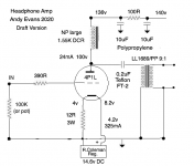
Update: I'm now on Version 3 of the parafeed designs, first being 6N30 with mains transformer output and second being 6J1P with NP amorphous plate choke and LL1689 OPT. Version 3 uses a 4P1L in filament bias with a large and OTT choke input filament supply. This is the stuff that's in my usual audio system. Kept the NP plate choke and LL1689.
Sound is pretty much there now. Clean and very detailed. The K701s are light on bass so I turned to the equaliser in iTunes, which I haven't used before. I looked at the K701 frequency response in Rtings - very useful site for headphones - and corrected it to flat as best I could, though only boosting the bass part way. Pulling the high treble down helped flatten the peakiness around 10K that seems to bedevil both headphones and microphones.
Volume is just about right. I have enough. The other improvement is putting more current through the tube. The 6J1P is rather wimpy and I was running it at 12mA. The 4P1L is running at 24mA.
I'll stay with this setup for a while. Possible changes would be SIC diode bias and using a gyrator. I want to try both but right now doing a lot of listening to my iTunes playlists. Sounds good on everything - classical, jazz and rock/electronic. Smooth and neutral. Easy to listen to and makes you forget the headphones are there, they don't seem to be in the way of the music.
Attachments
- Status
- This old topic is closed. If you want to reopen this topic, contact a moderator using the "Report Post" button.
- Home
- Amplifiers
- Tubes / Valves
- DIY Parafeed Headphone Amp