At the other end of the spectrum, comprehensive measurements (APx515) I took on a 6BL7 into a 10k:600 parafeed preamp showed low frequency distortion was strongly dependent on the size of the coupling capacitor. Transformers like being driven with low impedances. Larger sizes dramatically reduced the amplitude and harmonic number of distortion products.All transformers have parasitics which produce peaking.
Large in this context meant >100 uF before improvements became marginal. It's worth experimenting.
That is an interesting point, and partly why I mentioned my 0.68uF coupling capacitor.
Though it is 3x larger than Andy's, I didn't get much improvement in THD by using more capacitance. (THD @ 1kHz = 1%, 100Hz =1.5% or thereabouts)
I guess that the coupling capacitor value has much to do with the Rp driving it - something like a 6C33C would probably need 》100uF due to the very low Rp.
That being said, I will try it again when I have the lab time
The very small coupling capacitor in Andy's design is something I would definitely increase by a factor of 5 minimum.
I wouldnt have thought of it if it hadn't been mentioned by someone else!
Last edited:
A 100H plate choke and a 15K output transformer would tend to suggest 0.88uF for the parallel feed cap.
Thanks! Hadn't considered that but it makes perfect sense.I guess that the coupling capacitor value has much to do with the Rp driving it...
Thanks for reminding me that I need to look at the coupling cap. The only reason it's 0.2uF is that I prefer teflon caps to polypropylene caps. A couple of 0.1uF FT-2s in parallel already take up space. I could pile in several more if I had a larger case - I have plenty of the things. I'll try a larger polypropylene and see what that does and then try and do some careful listening over an extended period if the difference is subtle.
You mean I got something right rdf?
I must note the date and celebrate the occasion!
😱

Audiowize, had some Maths Fu there! Now I should dig out the books and look for the calculation!
I need to buy some of those russian teflon capacitors, but there are so many types, I dont know which are teflon.
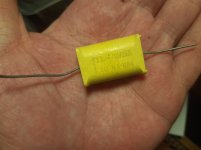
Andy, are they the green "K" types? I have just used what I have loads and load of; 0.68uf and 1uf 400V polyester and these film caps that i know nothing about (attached)
I must note the date and celebrate the occasion!
😱
Audiowize, had some Maths Fu there! Now I should dig out the books and look for the calculation!
I need to buy some of those russian teflon capacitors, but there are so many types, I dont know which are teflon.
Andy, are they the green "K" types? I have just used what I have loads and load of; 0.68uf and 1uf 400V polyester and these film caps that i know nothing about (attached)
Attachments
Last edited:
Russian teflons come in 2 types:
- K72. These are industrial strength in steel cases. Same inside I believe
- FT-2 (200v but can take more) and FT-3 (higher voltage, larger). These are smaller and lighter and come in aluminium cases.
Not much difference in sound. I prefer these to anything else. The green ones aren't teflon. There are also some dark grey metal caps which are paper in oil I believe. Some like them. There's also the silver mica caps in red box type cases. They're pretty good but I prefer teflon.
Gary Dahl's Espressivo was one of the first---probably the first---parafeed headphone amps I came across.
Espressivo Headphone Amplifier
t
Espressivo Headphone Amplifier
t
The Espressivo has an autoformer output - that's interesting. I have a pair of Slagle autoformers but never thought of them in this context. How would they work?
Update: Version 4 of the parafeed amps.
This is designed as a cheaper build. It uses the same 4P1L as in version 3, though this time in SIC diode bias. Plate choke is Hammond 126B, rated 44H and 30mA. OPT is a mains toroid at 230/12+12 giving 9.6:1 step-down.
I've been battling with some kind of ringing in these builds, and the likely suspect is the mains toroid. I unfortunately don't have the technology to see on a scope where this is coming from, and I've been using my 29 year old son as a "measurement system" since his HF hearing is excellent and he can hear at once if there is something physically unpleasant. So this version 4 comes with the caveat that there still appears to be ringing coming from somewhere. This was not present in version 3, with 4P1L, NP amorphous plate choke and LL1689 OPT. That was fine. Changes are SIC diode bias instead of filament bias, which I doubt is a culprit, different plate choke which I also doubt is a culprit, and the OPT which I think is the most likely problem. This is a shame since the sound is about 85-90% what the expensive version 3 provides. Without the ringing I'd be pretty happy with it. I switched the primaries of the OPT and that didn't fix it, though there was a mild improvement in the sound, and I previously found that I didn't like the sound effect of adding resistors across the output.
I don't know if I have the patience to swap over the OPTs - lots of unsoldering and unscrewing. Version 3 is working very well and sounding excellent, so I've ended up with a good headphone amp, which was the object of the exercise. I could revisit this when I have the technology to measure the frequency response but otherwise I'll probably leave it for now. This is a shame, since apart from the ringing it sounds excellent. US builders could easily substitute an Edcor OPT for the mains toroid, which would probably fix it. Anyway, here's the schematic.
Attachments

Andy,
I assume this mains toroid has a single primary?
I see the dual Secondaries.
Perhaps a silly idea (as you know I've been using 1/2 a dual primary/dual secondary transformer)...
What effect does it have if you only use a single secondary, and leave the other open circuit?
I dont think it'll make much difference, in my experiments, it made far more difference using only half the primary winding, as opposed to using half the secondary. But, secondaries in parallel were marginally the worst configuration.
Now none of this may apply quite the same, in you circuit..but perhaps a quick change, and easy experiment?
For what it's worth though you really should try to measure the frequency response of the various versions, it may be illuminating.
Last edited:
Much more useful than right. A valuable insight for future designs.You mean I got something right rdf?
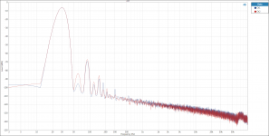
I think these spectrum measurements on the zero-feedback SE parafeed pre mentioned earlier were made with a 220 uF coupling cap. Not less than 100 uF. None of my amplifiers require more than 1 vrms drive for full output so that was the design target. The output transformers are ancient Freed 600:10K input transformers salvaged from early 1980s AM transmission equipment. Good modern transformers would likely do much better and I would expect the advantage of larger caps to be greater driving low impedance loads like headphones. These measurements were taken with 200K.
Attachments

- Home
- Amplifiers
- Tubes / Valves
- DIY Parafeed Headphone Amp