To prevent me from soiling the GB thread GB for Baby Huey PCB I'll be posting assorted pics here regarding my build.
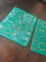
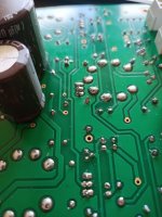
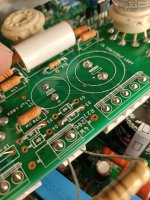
The rounding of the board and the thickness makes for a very nice looking board.
The rounding of the board and the thickness makes for a very nice looking board.
Attachments
Last edited:
I've decided to use schottkeys for at least the bias supply diodes. Perhaps also for the main psu rectifiers.
https://www.st.com/resource/en/datasheet/stpsc2h12.pdf
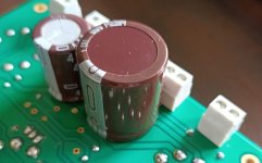
They do need some bending to fit. And I'll have to devise something so they don't touch each other. Should be no problem if I check after assembly if they don't touch.
https://www.st.com/resource/en/datasheet/stpsc2h12.pdf
They do need some bending to fit. And I'll have to devise something so they don't touch each other. Should be no problem if I check after assembly if they don't touch.
Hi Prasi,I am not sure if marc (bandol83 ) intended to populate them from bottom side .
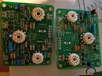
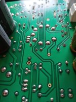
I populated the sockets from the top.
You gave me a big fright now.

I used this picture as my guide. But looking at the pcb I have in my hand....and the sockets....and the pcb tracks.... all looks good.
Attachments
Last edited:
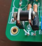
Nice solutionMy bias schottkey rectifier assembly just to prevent them from shorting...Just to be safe.
But couldn't you find any bigger diodes for 10mA rectified current ?
Mona
I tried. But mouser said the ones I ordered would be too heavy for airmailBut couldn't you find any bigger diodes for 10mA rectified current ?
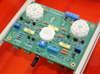
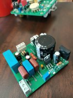
First test. Just the bias and powerdrive circuit.
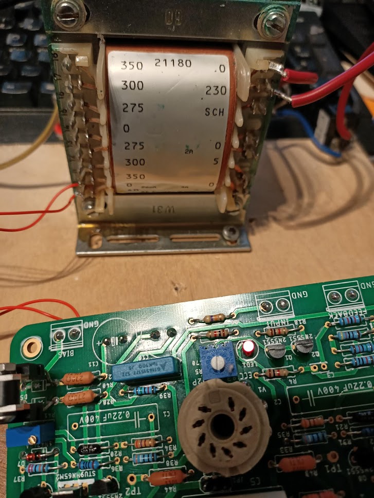
Test was successful.
No smoke. No explosions. Led lit up.
Bias was easily set by the little potmeters. 53VDC on the tabs of the powerdrive mosfet. Got confirmation from Gingertube that this is sufficient for the EL84 version.
Test was successful.
No smoke. No explosions. Led lit up.
Bias was easily set by the little potmeters. 53VDC on the tabs of the powerdrive mosfet. Got confirmation from Gingertube that this is sufficient for the EL84 version.
Last edited:
With regard to the discrepancies between the board 1.6 and the schematic 1.6. I used these values.
For
R16=15K
R17=10K
as per Schematic 1.6.
R18=1K
as on the Rev. 1.6 pcb.
Ofcourse the proof of the pudding is in the eating. I'll follow up on this.
R13 is 33k now but will be doubled up with another 33k after listening so I'll end up with 16.5k. (Just so I can hear the change for myself)
For
R16=15K
R17=10K
as per Schematic 1.6.
R18=1K
as on the Rev. 1.6 pcb.
Ofcourse the proof of the pudding is in the eating. I'll follow up on this.
R13 is 33k now but will be doubled up with another 33k after listening so I'll end up with 16.5k. (Just so I can hear the change for myself)
Last edited:
Of course the proof of the pudding is in the eating.
Thanks Bas, hope you pudding is superb!
Voltage across r18 is 1.056 volts. Perfect.
From member Planet IX
1,1/1000R=1.1mA
Measured is 1.056mA. So that each half of the triode is 0,5mA. Which is the target set by the designer.
From member Planet IX
Hi Bas,
if we assume Uled=1,7V and UbeQ2=0,6V then
Isink= (Uled-Ube)/R18
= 1,1V/560R
= 2mA
Regards, Boris
1,1/1000R=1.1mA
Measured is 1.056mA. So that each half of the triode is 0,5mA. Which is the target set by the designer.
Last edited:
21st century maida regulator:
21st Century Maida Regulator
21st Century Maida Regulator: A modern B+ voltage regulator – Neurochrome
21st Century Maida Regulator
21st Century Maida Regulator: A modern B+ voltage regulator – Neurochrome
Attachments
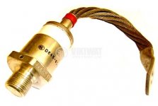
Try this one.I tried. But mouser said the ones I ordered would be too heavy for airmail
1200PIV 100(160)A
Attachments
- Home
- Amplifiers
- Tubes / Valves
- Oh no...not another Baby Huey EL84 build.