Baby and even more electron tube amplifiers have been made by me for years.
I haven’t finished one yet, but the classic Baby is in line. My hobby poisoned me.
I'm poor, I can't buy an output transformer. I have to make it.
I like the labels: "Classic EL 84 PP". That simplifies things in the future, no question about what type of design its good for!

Since I lost an output transformer and can't find it....I ordered new ones....as I'm sure the lost one will one day be found.
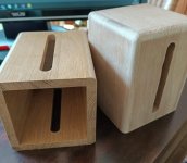
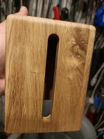
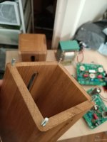
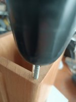
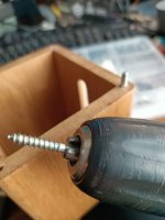
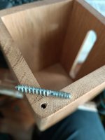
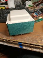
I'm prepping the enclosures for the transformers now. They are Ikea pencil boxes. I've used them before...but this time I thought why don't I route the sides round....
I'm prepping the enclosures for the transformers now. They are Ikea pencil boxes. I've used them before...but this time I thought why don't I route the sides round....
Attachments
Last edited:
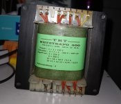
I've ordered local. Not only Dutch but also around 20km from me as the crow flies. The ones on the picture below are single ended ofcourse. But the ones I ordered are based on those cores.
Perhaps interesting. I've asked UL taps to be 25% instead of the ubiquitous 43%.
Perhaps interesting. I've asked UL taps to be 25% instead of the ubiquitous 43%.
Attachments
Last edited:
Hi Mac. I've used the single ended output c-cores before. In my 6v6 single ended amp. I am very happy with them. They are not cheap. But I know the craftsman who winds them. No rush jobs by a big company. He is a one man shop.Hey Bas! Tell us more about those transformers! Have you used them before?
What are the prices like compared to say Lundahl?
My PP EL84 cost 225 euros per pair. Home - Vlaartronic They would have been 175 in EI core versions.
I just bought power transformers from these guys. They also seem to have nice EL84 PP. 2 Stuck Gegentakt Ausgangsubertrager ATR 15 8000 Ohm Raa UL | TBT Trafobau
Last edited:
That is cool! It is always good to have another transformer supplier. Especially one who cares about quality and craftsmanship...
I feel like it is worth the extra money for the knowledge that the trafos are well made and quality units. and supporting a one man shop in the Netherlands. Thanks for the info!
I feel like it is worth the extra money for the knowledge that the trafos are well made and quality units. and supporting a one man shop in the Netherlands. Thanks for the info!
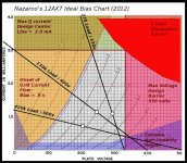
Voltage across r18 is 1.056 volts. Perfect.
From member Planet IX
1,1/1000R=1.1mA
Measured is 1.056mA. So that each half of the triode is 0,5mA. Which is the target set by the designer.
Bas, I’m checking things again before I push the button to buy my parts, and I noticed you stated the designer aimed for 0.5 ma per 12ax7 triode. On my schematic, dated Nov 19, 2018, it shows 2.5 ma for the combined tail current (see just below R5). Am I looking at the wrong schematic? It shows R18 as 560 ohms.
I also wondered if you used gingertube’s recommendations (that he recently gave for BHEL34 builders).
1. Replace R17 with red LED and adjust R16 for 2ma thru LEDs
2. R3,4 changed to 4.7k
3. R33,38 changed to 270
4. R14,15 changed to 1k
I also wondered why you changed R20,21 to 500k. I think you referred to them as the grid resistors, but the output tube grids get grid grounding via R33,38 and the bias supply, not R20,21. Did I misunderstand?
Sorry about your missing OT, but I think it will show up shortly for your second BHEL84 stereo amplifier.
The 2,5mA is I believe meant for the EL34 version which has higher b+.On my schematic, dated Nov 19, 2018, it shows 2.5 ma for the combined tail current
The original baby huey el84 was aiming for around 1mA/1,2mA. Someone pointed that out to me and did the math. I think he was right on that count.
Oops did I refer to them as grid resistors? I meant grid leak/bias resistors. I believe textbook for fixed bias (EL84) is max 200k (Don't know why though). I don't think it really matters if its 1meg or 500k. Thats why I said...that is what I did..but it is not a recommendation on Ian's part (or mine for that matter...sometimes I just do ****I also wondered why you changed R20,21 to 500k
the way I "feel" it should be).Some post I just found googling: Amplifiers that exceed grid leak resistance
Last edited:
So no I did not...see my post above. And where I asked the question in my own thread: Could you check the values for this current source?I also wondered if you used gingertube’s recommendations (that he recently gave for BHEL34 builders).
Sorry about your missing OT, but I think it will show up shortly for your second BHEL84 stereo amplifier.

Last edited:
So no I did not...see my post above. And where I asked the question in my own thread: Could you check the values for this current source?
Bas,
Thanks for the link to your other thread. Somehow I missed it.
I looked at the 12ax7 loadlines at 0.5 ma fixed by the CCS. I expect ~130v on the plates (310/440*189) based on gabo‘s post in the BHEL34 thread. He measured 189v on the 12ax7 plates for his EL34 build with 440v B+, and with his R18 at 680k. That seems to be a better operating region in the loadlines, than the one for BHEL84 under the conditions mentioned.
Since Ian designed the BHEL84 to run 0.5 ma on the 12ax7 triodes (based on your review of the thread) something could be wrong in my analysis. I hope someone more knowledgeable could help to explain the apparent discrepancy.
It would be very helpful if someone with a completed BHEL84 could measure your plate voltage, cathode voltage and voltage across R18 (assuming 1k, or mention what was used)
Attachments
Since it is a design issue that could be of interest to others not involved in this builders thread, I reposted my post above (#56), with some additions, to the original Baby Huey thread here:
EL84 Amp - Baby Huey
EL84 Amp - Baby Huey
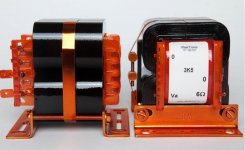
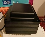
While there is beauty in a big bad *** black power transformer. I don't like the way it shows dust. And prefer something lighter. Hence the repaint (something I try to keep to a minimum...as painting is tedious, takes time and is in my experience easily damaged. Not a 100% sure I'm going with this transformer yet. But it is on the table.
Attachments
Last edited:
- Home
- Amplifiers
- Tubes / Valves
- Oh no...not another Baby Huey EL84 build.