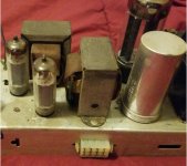
The chassis is stamped 5U4.Good eye.
I went through my old Magnavox service data, and the Amp197 chassis is almost identical.
Although, it seems the OP's unit has a 5U4 rectifier installed, instead of the stock 5Y3.
Not a wise choice for that chassis.

Ok, so that particular chassis was "part" of the system it was in. - likely a console model.
Using such a high-current rectifier like the 5U4 means it was also required to power a tuner/preamp chassis - the rectangular knockout on the side once held a molex connector for that.
Since now it's used in "stand alone" service, I'd use a 5Y3GT instead, to give the chassis and power transformer a break since it's "on-chassis" load is now only those 3 audio tubes.
The other chassis I mentioned, Amp197, was used alone, and used the 5Y3 for "phono only" duty.
The chassis should have an ink-stamped version number on it.
Like..... AA196-XX
Thank you for that. Yes, there are two ports on the side. The tuner power port looks like it might never have been open, not sure.Ok, so that particular chassis was "part" of the system it was in. - likely a console model.
Using such a high-current rectifier like the 5U4 means it was also required to power a tuner/preamp chassis - the rectangular knockout on the side once held a molex connector for that.
Since now it's used in "stand alone" service, I'd use a 5Y3GT instead, to give the chassis and power transformer a break since it's "on-chassis" load is now only those 3 audio tubes.

The other chassis I mentioned, Amp197, was used alone, and used the 5Y3 for "phono only" duty.
The chassis should have an ink-stamped version number on it.
Like..... AA196-XX
There are two numbers on the chassis. One ink-stamped and one mechanically-stamped.


Helpful.FYI, that is a Magnavox AA-196.
MAGNAVOX STEREO SE SINGLE ENDED TUBE AMPLIFIER 196-AA | eBay
there are two ports on the side. The tuner power port looks like it might never have been open, not sure.
Attachments
Interesting. Thanks Allen.
I've done a little study of this "death cap" that was mentioned earlier. I now have some rudimentary idea of what it is, what it was meant to do, and what it can do in certain situations.
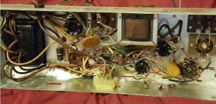
There is a ceramic disc (?) capacitor wired across the hot and ground leads coming in to the amp. But it is a three lead capacitor, the third lead is wired to chassis ground. See pics.
My impression is that if the amp is correctly converted to a three wire power cord, then a death cap could/should be removed. But the cap in question on my amp does not quite match what I've read about how death caps are usually wired.
So it's an AMP-597-00, not a 196 as claimed.
The WHITE striped AC cord wire is the GROUND side - going to the WIDE blade of the plug.
That is how it's supposed to be wired, per electrical code.
And those "flying connections" are dangerous slop messes that amateurs do.
All parts and wires have to be anchored to tag strips, not left unsupported in the air like that.
That amp needs proper attention and re-wiring, among other things.
Last edited:
Hmm, ok. Thank you.So it's an AMP-597-00, not a 196 as claimed.
Yes, you pointed that our earlier, thus that is how I represented the power leads in the picture. As wired, not as they should be.The WHITE striped AC cord wire is the GROUND side - going to the WIDE blade of the plug.
That is how it's supposed to be wired, per electrical code.
I assume this means two components soldered together at a point in midair. For sure in a high vibration environment this would be bad, but then one would not be soldering anything, it would all be crimped connections.And those "flying connections" are dangerous slop messes that amateurs do.
Maybe thermal expansion and contraction could cause the joint to flex and crack eventually? Sitting here with the amp in from of me, I only see one such connection. But trained eyes might spot more.
I have not personally done anything to this amp. I'm just trying to learn.That amp needs proper attention and re-wiring, among other things.
wiseoldtech, do you have any comments on the "death" capacitor?
Yes, the ceramic cap is wired across the AC mains, and the third capacitor terminal is wired to chassis ground. There is no "ground switch".FWIW, that ceramic cap. appears to be wired across the AC mains. It also appears to be unswitched.
I will look at it, thanks.If something like this can fit, you will get better protection against "nasties" riding on the AC power mains.
Eli..Agreed, the orange double section disk cap appears wired directly across incoming AC from the wall without the benefit of the fuse; this could be a fire hazard. A shorted section of that cap could put line voltage on the chassis (the death trap) since there is no 3 wire cord and plug to ground the chassis. Looks like the fuse protects (using a low voltage holder) only the power transformer. Looks like the RHS side of the disk cap appears to support some wiring; this is really not kosher...Also looks like there are some cold solder joints.
Last edited:
wiseoldtech... good idea on the polarized line cord. In my years I have not had a power transformer short to chassis, primary or secondary....
NE Philly? I lived off the Boulevard and Grant Ave for a while years ago...
NE, yes, born 'n raised.
Gotta hit the Lowes Grant/Blvd soon come spring, for some lumber and stuff.
You musta retired, most of my elder friends retired and moved "out west" to Wellsboro and Jersey Shore Pa.
Lovely areas.
The neutral line cap-to-chassis keeps a lot of noise down, and helps reception in tuners/radios.
Just about anything "vintage" benefits from converting to a polarized cord.
Last edited:
Thanks, that is the way I see them in my studies.I see no need for those "double caps" used as line filters.
I usually install a 0.01u to 0.047u-630v cap from chassis to the ground side of the (polarized) line cord.
Never had an issue with this way.
- Status
- This old topic is closed. If you want to reopen this topic, contact a moderator using the "Report Post" button.
- Home
- Amplifiers
- Tubes / Valves
- Vintage Tube Amp Hissing and Popping