Just do the MathYour comment that grid stopper resistor does not affect sound got me curious DF96.
Why would it not be when this resistor is directly in the signal path.
Thanks
")
* 1k or 1k3 in series with a zillion ohm impedance does little to nothing.
* 1k or 1k3 in series with a 30pF cuts off frequencies above 5.3MHz or 4MHz so way way above Audible range.
Nobody said they sound betterI am still not getting why the carbon comps are BETTER as a grid stopper resistor than a metal film one. WHAT makes them SOUND better?
I guess they are better as grid stoppers because in principle they are less inductive than other types and have been favored by Hams for decades now.
How about a good old carbon film, it's non-metallic, the resistive material that is.
Out of curiosity I am wondering too why carbon composition would be a preferable grid stopper, I am aware of its inherent noticeable distortion component which may attract some people for it's subjectively audible niceness, but I would rather thinking of what advantages and properties it has in curbing oscillation and attenuating incoming RF pollution from the ether.
Out of curiosity I am wondering too why carbon composition would be a preferable grid stopper, I am aware of its inherent noticeable distortion component which may attract some people for it's subjectively audible niceness, but I would rather thinking of what advantages and properties it has in curbing oscillation and attenuating incoming RF pollution from the ether.
Anatoly and Mr Kronye are right.
Only if necessary, install a grid stopper. Then put on that resistor that you like the sound of.
Personally, in tube diy, I always use a Caddock MP915 or MP930 (with ot w/o heathsink) NI metal film resistor.
They are quite cheap at my dealer.
Best diying.
Only if necessary, install a grid stopper. Then put on that resistor that you like the sound of.
Personally, in tube diy, I always use a Caddock MP915 or MP930 (with ot w/o heathsink) NI metal film resistor.
They are quite cheap at my dealer.
Best diying.
One K CC resister thermal noise is in the microVolts, orders of magnitude less than the equivalent noise resistance of the 12AX7. Do the math, all covered in great detail in text books of the vacuum toob age. If there are noise problems you can hear from a power amp with the gain set to zero, better start looking elsewhere for the problem.
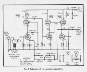
A low noise front end requires a Hi-G triode, run a high plate current. A cascode setup works well, low noise & reasonable gain. Usually low noise is only needed for low level sources like magnetic phono pickups.
12AY7 is a low noise alternative to the 12AX7. Pin for pin plugin in, adjust the bias.
Look out for microphonics, the ancient toobs favored by some make good microphones, create lots of headaches for the adventurous.
The cascode example is from the 50's. I tried it, dead quiet.
Attachments
FWIW I almost always use 1% MF types of between 180 and 1000 ohms for the grid stopper. I also use metal oxide types for cathode/plate stoppers where necessary (current sharing of parallel tubes mainly), between 10 and 47 ohms. Carbon comp resistors are great because they are easy to see the colour bands on with my eyes, and they "look cool" from a nostalgia perspective, but they aren't great in a humid environment and they cost 100 times more than MF.
metal and carbon film resistors are spiral formed, this is a intrinsic part of the build and calibrate process.
Carbon composition is massive and has no built-in spiral, thus less inductance.
For use as grid and scree stoppers they should be as little inductive as possible and mounted as close to the grid as possible.
Carbon composition is massive and has no built-in spiral, thus less inductance.
For use as grid and scree stoppers they should be as little inductive as possible and mounted as close to the grid as possible.
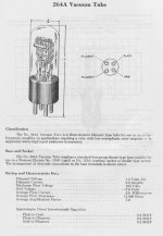
Ancient Low Level Toob for Low Microphonics
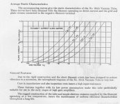
For those who still want to use a relic in the amp front end the 264 or 864 will fill the low microphonics requirement. Built from the bottom up to be free of microphonics..
For those who still want to use a relic in the amp front end the 264 or 864 will fill the low microphonics requirement. Built from the bottom up to be free of microphonics..
Attachments
As has been stated before, CC resistors are as close to non-inductive as you are likely to see. I've never had problems using a metal film resistor as a grid stopper, but that's not to say it can't cause problems. Increasing the value from 1K to 1.3K will probably have a negligible effect in all likelihood. Lots of people just throw a 1K grid stopper on every tube "just to be safe". I agree with Wavebourn- It's better to see if it is actually necessary than to just throw them in everywhere.
There's another point that was mentioned only briefly, and I think deserves a bit more attention. CC resistors handle surge currents (and high voltage) considerably better than other types like metal film and even wirewound. Metal film resistors can instantly open as the laser-cut metal film vaporizes, and I have yet to see a CC resistor do this. Wirewound resistors can also do this, and I have seen it on multiple occasions. If you look at most discharge sticks for very high voltages (10kV+), you will see that (if properly made), they use big carborundum resistors for this very reason. In grid stopper duty, this is a moot point since the current through it is negligible.
There's another point that was mentioned only briefly, and I think deserves a bit more attention. CC resistors handle surge currents (and high voltage) considerably better than other types like metal film and even wirewound. Metal film resistors can instantly open as the laser-cut metal film vaporizes, and I have yet to see a CC resistor do this. Wirewound resistors can also do this, and I have seen it on multiple occasions. If you look at most discharge sticks for very high voltages (10kV+), you will see that (if properly made), they use big carborundum resistors for this very reason. In grid stopper duty, this is a moot point since the current through it is negligible.
Your comment that grid stopper resistor does not affect sound got me curious DF96.
Why would it not be when this resistor is directly in the signal path.
Thanks
it does 0 difference, in good designs you can play poker and remove them all, but it should be there as per scientific knowledge of amplifiers....
I use 10K for that type of tube.
0 difference with costly resistors too... (tantalum , carbon etc, 0 effects )
I only suspect that if you have directly coupled higher voltage like 300V+ a special resistor can help such as over 500V certified resistors... do no expect any sound difference.
I found in solid state designs that I preferred cheap flame proof resistors for some reason, I built the same designs with each pcb boards filled with different types of resistors. I tried others like rikken (they have effects on sound in proper places like plate resistors) dale, and many others, PRP and caddock as well as foils, they should be used for Mhz applications, not for audio, no need for that.
The "wisdom" from the golden age of tubes was for a grid stop on a triode to be 8/gm (to guarantee freedom from parasitic oscillation). For a new 12AX7 (gm=1.6mA/V) that is 5K. For a 12AX7 at "replace me now" gm of 1.6 x 70% = 1.1mA/V that is 7K2 I put 10K on all 12AX7 amp builds as routine.
If 10K does not stop the oscillation then a larger gridstop will NOT help. Look elsewhere for the problem. Note that higher gm tubes need smaller gridstops. A 6DJ8 (EXCC88) with a gm of 15mA/V would need 533 Ohms. This (inverse relationship to gm) applies to output tubes too. The 1K5 you see on EL34 is NOT enough for 6L6 or 6V6.
Cheers,
Ian
Do the maths of a potential divider and you will see that a grid stopper of the correct value cannot affect the sound, even when you take Miller capacitance into account.sumotan said:Your comment that grid stopper resistor does not affect sound got me curious DF96.
Why would it not be when this resistor is directly in the signal path.
Don't be lead astray by spurious arguments based on 'signal path'.
No, the aim is to minimise stray capacitance at that circuit node. A resistor plus a piece of wire will have the same inductance whichever order they come in, but the stray capacitance will be different.SemperFi said:The whole point of 'place grid stopper right at the pin' is to introduce as little stray inductance as is physically possible.
No, that is not the main purpose of a grid stopper although it may provide an LP filter for incoming RF in addition to its main function, which is to reduce the Q of the grid circuit when seen as an RF resonator.Hanze Khronye said:If all we are doing is creating a LP filter, why not small value cap in parallel with the grid leak resistor?.
Yes, as close as possible. No, a little inductance will usually do no harm and in many cases will help. RF amplifiers often use lossy inductors as stoppers; audio amplifiers are generally easier to tame and so we can use a simple cheap slightly inductive resistor.petertub said:For use as grid and scree stoppers they should be as little inductive as possible and mounted as close to the grid as possible.
A small cap from the grid to the ground in some cases works better than a grid stopper, as I pointed already above. You should analyze pretty complex system when designing for stability that includes parasitic inductances and capacitances inside of the tube and around. They couple where we don't want, they add phase shifts and resonant tanks that we do not want. Most often we do not need any stoppers, but when we do, we have options, how to change that complex resonant system with parasitic positive feedbacks.
Rules of Dumbs like "Always use CC resistors near all grids" do not work here.
Rules of Dumbs like "Always use CC resistors near all grids" do not work here.
For those who still want to use a relic in the amp front end the 264 or 864 will fill the low microphonics requirement. Built from the bottom up to be free of microphonics..
Probably first saw application as a photophone pre-amplifier (movie audio repro amp)
No, the aim is to minimise stray capacitance at that circuit node. A resistor plus a piece of wire will have the same inductance whichever order they come in, but the stray capacitance will be different.
I don't quite agree. I'd want the damping resistance as close to the active part, the tube internals, that has the gain that may oscillate due to stray reactive components, and with as little inductance -or antennae- as possible in between.
The grid stopper separates the outside parasitic inductance (ok - and capacitance - reactive components) from the tube's own internal capacitance. The inductance and the capacitance creates the oscillating circuit, with the tube's gain of course. (Can a cathode follower oscillate the same way? I have experienced MOSFET followers oscillate without gate resitors, and there should not be gain in a follower, but the oscillation stopped with the gate resistor. hmmm)
(I know the antennae part of wire must be several inches before it really is an antennae... or does it? Todays world with SMPSs switching with ns flanks.) To me I see no reason not to place the gridstopper right at the pin, and the reason is to limit unwanted inductance, as well as having a logical and consistent place to have it.
Rules of Dumbs like "Always use CC resistors near all grids" do not work here.
It may be rules of dumb but I have had MF gridstoppers open up after over-drive in guitar amps. CCs have never failed, they are simple the most tolerant resistor types. And the horrid drift doesnt matter in this application, so I see no reason not to adhere to this rule made up by much wiser men than me.
FINALLY, someone with solid reasoning! Thank you!It may be rules of dumb but I have had MF gridstoppers open up after over-drive in guitar amps. CCs have never failed, they are simple the most tolerant resistor types. And the horrid drift doesnt matter in this application, so I see no reason not to adhere to this rule made up by much wiser men than me.
Thanks for tip. Will add to my list of thumb rules.The "wisdom" from the golden age of tubes was for a grid stop on a triode to be 8/gm (to guarantee freedom from parasitic oscillation). <snip>
You may have popped a screen grid stopper, but trust me you have not popped a control grid stopper that way.I have had MF gridstoppers open up after over-drive in guitar amps.
- Status
- This old topic is closed. If you want to reopen this topic, contact a moderator using the "Report Post" button.
- Home
- Amplifiers
- Tubes / Valves
- Grid stopper resistor question