Hi,
looking at your diagram, are you really supplying the el84s with 340v?
It's a long time since I used these, but that sounds a little high.
regards john
That is not his amp. That is a TCJ schematic that I posted to show him how to connect a screen stopper. That is somewhat over spec for some EL84s. Russian -EV tubes are OK I think.
TVS diode wired directly in parallel with the output jack should be completely inaudible, and save huge 200v bangs from loose connections or tube faults from destroying a high dollar marantz amp. They have some # of picofarads of capacitance which is probably less than the RCA coax cable to the power amp.PS. So, how do I wire the diode into a circuit?
Please use a muting circuit with a relay at the output of that preamp to prevent blowing up speakers when the preamp is switched on or off when the power amplifier is still switched on. This counts especially with DC coupled amplifiers but it is simply good practice in any amplifier case. It should release outputs after 30 seconds at power up and it should short the outputs immediately at shutdown. Series resistors 47 Ohm from each of the 1 megaOhm resistors to the relay contacts can make you feel better.
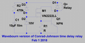
Is this what @wavebourn is referring to in post #31?
I'll admit, I don't fully understand the schematic in post #31.
Where does the signal enter? Where does the ac/dc power enter the circuit. Does it use B+ or heater Ac power?
What type of specs does one look for in a relay?
What are the non-numbered "D" and "R" letters for?
What transistor should I use for NPN?
What is M1?
Maybe there is a write up on this circuit somewhere to help me understand it? I scanned through wavebourns threads on the forum, but didn't see a title that indicated it was about muting circuit.
It is that "if"One will definitely learn after the first set of burned woofers (by accident, by a partner or child). A muting circuit costs way less than a set of woofers, adds convenience and removes a risk.
Your position is the "if", not mine. I troubleshoot to actual observed symptoms.
We can get caught up in semantics but a muting circuit prevents damage at a very low cost and protects valuable devices. The constant need to focus on the "right" power up and power down sequence is not convenient.
Your troubleshooting to actual observed symptoms should tell you the same. I repaired many amplifiers and speakers because of the lack of protection circuits.
Besides that, who is worried about 10$ extra cost that takes away risk and has no negative side effects? It differs with various devices but experience tells that exactly the device that has no bad power up or power down phenomenons is the one that fails one day taking away the woofers.
I aks myself why there alway seem to be the need to explain simple good practice items like muting circuits, gate stoppers, input filters etc? Any mass produced quality device has those.
Last edited:
True but my gut feeling tells me that when that problem is solved (probably oscillation) the other described phenomena are waiting around the corner. Adding the suggested input RC filering might be of some help in solving the issues.
It would help tremendously if OP replies to posts.
It would help tremendously if OP replies to posts.
Last edited:
Have you considered the suggestion I made about mains voltage variations getting though the PSU and the preamp? There is a frequency band around 0.5Hz which is not attenuated much by either of them. To solve this problem you would need a bigger cap in the PSU or a smaller cap in the preamp, so the passbands no longer overlap.
Dedicated circuit, mains filter etc. will do nothing to protect you from mains voltage variations. If your mains goes from 110V to 115V then the supply rail voltage will increase and some of this increase will appear at the amp output.
The PSU cap to make larger is the 1uF feeding the valve grid. Alternatively (or in addition) reduce the 4.7uF output cap. The aim is to ensure that there is no overlap between the passbands of the PSU low pass filter and the amp high pass filter.
You could do a check. Attach a meter to the supply rail and see if the DC voltage varies by much. You may need to watch it for a few minutes.
If the output network was 1uF and 47k load, the subsonic cutoff would be about 4Hz, not 0.03Hz, at the expense of slight gain reduction.
Adding a bidirectional TVS diode across the output would tame the voltage excursions on turning on and off to levels that won't blow up a front-end. Without this the existing output stage can source upto about 50mA or so at upto 220V, not semiconductor safe.
Adding a bidirectional TVS diode across the output would tame the voltage excursions on turning on and off to levels that won't blow up a front-end. Without this the existing output stage can source upto about 50mA or so at upto 220V, not semiconductor safe.
- Home
- Amplifiers
- Tubes / Valves
- DIY Tube Preamp causing Power Amp Protect Mode