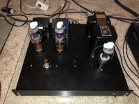
It looks like the metal tabs of each 317 is attached to the chassis.Yes. The bypass cap is not pictured here, but the 317 is.
I cant see if there is anything isolating them. I would isolate them, if they are electrically connected to the chassis.
OK, Lets blame the 317? Sounds like it might be used beyond its rated limits, or application requirements. There is no Heat Sink on the 317. It may not need one, but check. I will guess that the 807 self bias is about 15V. At 45mA that is only 0.675 Watts, OK.
What is the uF value of the bypass cap? Are you using a wire-wound resistor for the LM317 current sense resistor? A 250 Ohm resistor works better, then why not use that? No, let us get the CCS working for you. How about posting a full schematic of your amp, with voltages marked? That would be so helpful. Plus, I always enjoy looking at others schematics.
LM317 bypassed: I believe that if a (any) CCS is bypassed with a large capacitor, that the linearity of the CCS does not matter (unless you are driving the SE amp into hard clipping).
LM317 unbypassed: I have used LM317 as a CCS for long tail phase splitters before, and I did not have any non-linearity problems.
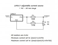
The LM317 requires a minimum of 3V from input to output, and a minimum current of 10 mA (is rated for Typical operation at 3mA). But with 3V across the device, you also need 1.25V for the sense resistor. That means the burden voltage of the LM317 as a current source (or Sink in this case) is 4.25V Anything below 4.25V might cause the current to collapse.
Like all semiconductors, I put a clip on the lead next to the body when I solder them into the circuit. That prevents them from overheating during soldering. Works for me, I have not checked to see if I can get away without doing that.
===
I read more carefully. You have a 100uF bypass cap. That is 80 Ohms @ 20 Hz. An 807 transconductance = 6,000 micromhos (250V plate, 250V Screen, and -14V grid). That puts the cathode impedance at 167 Ohms (it is larger than that because the plate is driving a real load impedance). But think of bypassing a cathode's 167 Ohm impedance with the bypass cap's 80 Ohm impedance. 100 uF bypass cap works better with a 250 Ohm self bias resistor than it does with a CCS.
You had 45 mA from the current source. You had 18V on the cathode. 18V and 250 Ohm resistor gives 72 mA. A Generalization: The 807 SE amp will give more output power at 72 mA than at 45 mA.
Just some things to think about.
What is the uF value of the bypass cap? Are you using a wire-wound resistor for the LM317 current sense resistor? A 250 Ohm resistor works better, then why not use that? No, let us get the CCS working for you. How about posting a full schematic of your amp, with voltages marked? That would be so helpful. Plus, I always enjoy looking at others schematics.
LM317 bypassed: I believe that if a (any) CCS is bypassed with a large capacitor, that the linearity of the CCS does not matter (unless you are driving the SE amp into hard clipping).
LM317 unbypassed: I have used LM317 as a CCS for long tail phase splitters before, and I did not have any non-linearity problems.
The LM317 requires a minimum of 3V from input to output, and a minimum current of 10 mA (is rated for Typical operation at 3mA). But with 3V across the device, you also need 1.25V for the sense resistor. That means the burden voltage of the LM317 as a current source (or Sink in this case) is 4.25V Anything below 4.25V might cause the current to collapse.
Like all semiconductors, I put a clip on the lead next to the body when I solder them into the circuit. That prevents them from overheating during soldering. Works for me, I have not checked to see if I can get away without doing that.
===
I read more carefully. You have a 100uF bypass cap. That is 80 Ohms @ 20 Hz. An 807 transconductance = 6,000 micromhos (250V plate, 250V Screen, and -14V grid). That puts the cathode impedance at 167 Ohms (it is larger than that because the plate is driving a real load impedance). But think of bypassing a cathode's 167 Ohm impedance with the bypass cap's 80 Ohm impedance. 100 uF bypass cap works better with a 250 Ohm self bias resistor than it does with a CCS.
You had 45 mA from the current source. You had 18V on the cathode. 18V and 250 Ohm resistor gives 72 mA. A Generalization: The 807 SE amp will give more output power at 72 mA than at 45 mA.
Just some things to think about.
Great replies! With the 250 ohm resistor, I see about 13V on the cathode or 52mA. Yes, that will still make more power than 45mA, but should not make double the power and 52mA at 380V B+ is about as high as I’d take the 807 at 19.7W plate dissipation.
I just can wrap my head around the 317 collapsing. Seems like a very easy load to the IC.
I just can wrap my head around the 317 collapsing. Seems like a very easy load to the IC.
deicide67,
I can not see a Good and Working LM317 collapsing there either.
Is the sense resistor a wire-wound? I Could see that same LM317 oscillating at a particular voltage if the sense resistor is inductive. The cathode voltage changes in a SE amplifier when the signal is large, bypass caps cause that, because SE has second order distortion, draws more than 2X the quiescent current, but no less than 0 current, even at clipping.).
I agree, run the 807 at up to 20W, but no more. That gives a 20% margin. And there is another 5.67W of heat from the filament in the same glass envelope.
380V - 13V = 367V (13V on the cathode) 367V x 0.052A = 19.1W And B+ can be lower than 367V (another voltage drop through the DCR of the OPT primary).
Maybe we need to try another LM317. Or you can go self bias with a resistor. In either case, I would use more uF for the bypass cap.
Last edited:
I tried every cap I had across the CCS, and while it varies the frequency response some open loop and with feedback, it still made a bit less power than the resistor. I will try added resistance plus the CCS tomorrow. I agree with previous posts that with less voltage across it to misbehave, it may work better.
I don’t have a schematic at this point, but could draw one up.
Thanks everyone!
I don’t have a schematic at this point, but could draw one up.
Thanks everyone!
I'm not expert or even slightly experienced with valves. I'm even less experienced in using CCS (100%) Something simplistic occurred to me however. Can you measure/imply the grid current? Is it possible that the regulator is going wobbly when you drive the valve grid positive? I.e. you experience no issues while no significant current flows, but once into positive grid volts the current upset the CCS? Just a simple thought (I'm probably wrong) but something to eliminate, perhaps?
decide67, you have measured the dc voltage of the cathode at idle, but I don't see any cathode voltage measurements with large signal - ie. to indicate if there is a dc bias movement as signal increase, and what is the AC voltage signal (ie. does the voltage across the 317 bottom out to less than about 3V, or increase to a level in excess of max rating).
decide67, Be sure the bypass cap goes all the way from the 807 cathode to ground. It must go across both the LM317 and the sense resistor (LM317 and sense resistor are in series). If there are any other resistors in the 807 Cathode, you need to post the schematic. And if you are using any feedback to the 807 Cathode, you need to post the schematic. Again, the minimum working voltage across the LM317 plus its current sense resistor is 4V. What is the 807 screen connected to, a series resistor to B+ (how much resistance?), a regulated supply, UL tap, or what? Lets get this problem solved.
Thanks everyone for your input!
I now have the LM317 performing nearly equal to the simple cathode resistor. I have 273V on the plates with 288V B+, LM317 set to 52mA for just under 20W plate dissipation, 210V regulated G2 voltage. I get nearly 7W. I was getting a bit more but backed down the idle current to 52mA vs 56mA. The schematic has a bit of schade feedback and some global as well. I pulled the global, but adding it back leveled out the bass performance a bit.
Thanks again!
Attachments
- Status
- This old topic is closed. If you want to reopen this topic, contact a moderator using the "Report Post" button.
- Home
- Amplifiers
- Tubes / Valves
- LM317 as CCS