Love him or hate him ... I am a big fan of Thorsten since day 1. His designs are elegant but simple and he uses a common sense approach to design.
I am looking to build a tube preamp with phono stage and stumbled across his "Valve El Cheapo". This seems a good compromise of the various phono stages I looked at.
I plan to couple that with his parallel 6SN7 line stage design. I have already prototyped the line stage with some NOS Sylvania Bad Boys and it sounds incredible. One of the best tube line stages I have heard to date!

Power will be supplied with a SSHV2. I am thinking of putting the power transformer, rectifiers and initial filtering in a separate chassis. My only concern is I am considering AC heaters and not sure it is a good idea to run AC heaters in the same power umbilical cable as rectified B+? Worst case I can just build an unregulated DC supply in the PS chassis for the heaters.
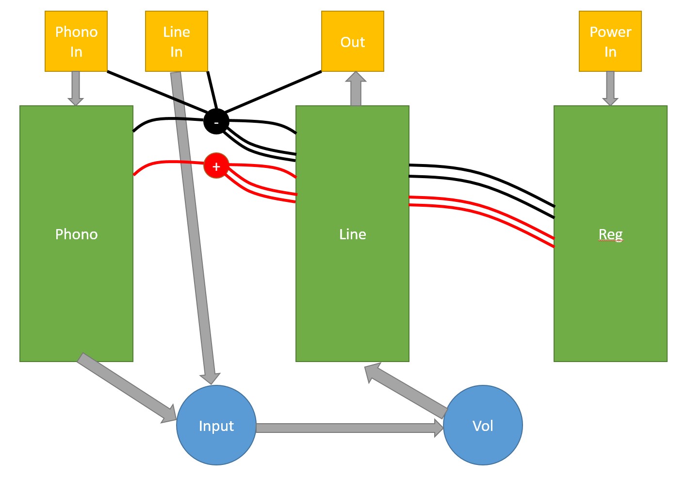
I read through Allen Wright's Preamp Cookbook and his grounding and wiring suggestions make sense as I am a PCB designer by trade and it is ALL about return currents! Here is my intial concept for the preamp chassis. I know the SSHV2 sense wires need to be as close to the load as possible so I am looking to install Power and Ground lug terminals between the 2 turret boards and sensing at that point where I branch off to each circuit. Is that close enough to be effective? I considered one SSHV2 per circuit but it seems a waste since the line stage only draws ~12ma vs the phono ~30ma.
For a chassis I am thinking about the Dissipante so I can utilize one of the heatsinks for the SSHV2 yet keep the entire preamp enclosed in a metal enclosure. One of the concerns is tying the preamp enclosure to DC GND with a 250VDC potential inside. Is this safe vs. traditional IEC "Earth" grounding when AC is present (which I plan to do in the PS chassis)?
The preamp will be point-to-point wired on turret boards like this using solid core silver wire with PTFE insulation for signal and heavier solid copper for power.

Other mentionables are a motorized TKD volume pot for adding remote volume later, Elma input (1 phono + 2 aux) and output switching. I decided to do a 3-way output to work with all of my systems. First is my modified Klipschorns powered by a CX-345 TSE (soon to be DIY Pass F7) that is my "critical" listening setup. Second is a Modulus 86 driving Snell Type E's when I just want to jam and third will be my headphone setup.
I'll keep everyone posted on the progress and pictures in this thread. Please feel free to comment or make suggestions along the way as I intend this build to hold me over for some time to come.
I am looking to build a tube preamp with phono stage and stumbled across his "Valve El Cheapo". This seems a good compromise of the various phono stages I looked at.
I plan to couple that with his parallel 6SN7 line stage design. I have already prototyped the line stage with some NOS Sylvania Bad Boys and it sounds incredible. One of the best tube line stages I have heard to date!
Power will be supplied with a SSHV2. I am thinking of putting the power transformer, rectifiers and initial filtering in a separate chassis. My only concern is I am considering AC heaters and not sure it is a good idea to run AC heaters in the same power umbilical cable as rectified B+? Worst case I can just build an unregulated DC supply in the PS chassis for the heaters.
I read through Allen Wright's Preamp Cookbook and his grounding and wiring suggestions make sense as I am a PCB designer by trade and it is ALL about return currents! Here is my intial concept for the preamp chassis. I know the SSHV2 sense wires need to be as close to the load as possible so I am looking to install Power and Ground lug terminals between the 2 turret boards and sensing at that point where I branch off to each circuit. Is that close enough to be effective? I considered one SSHV2 per circuit but it seems a waste since the line stage only draws ~12ma vs the phono ~30ma.
For a chassis I am thinking about the Dissipante so I can utilize one of the heatsinks for the SSHV2 yet keep the entire preamp enclosed in a metal enclosure. One of the concerns is tying the preamp enclosure to DC GND with a 250VDC potential inside. Is this safe vs. traditional IEC "Earth" grounding when AC is present (which I plan to do in the PS chassis)?
The preamp will be point-to-point wired on turret boards like this using solid core silver wire with PTFE insulation for signal and heavier solid copper for power.
Other mentionables are a motorized TKD volume pot for adding remote volume later, Elma input (1 phono + 2 aux) and output switching. I decided to do a 3-way output to work with all of my systems. First is my modified Klipschorns powered by a CX-345 TSE (soon to be DIY Pass F7) that is my "critical" listening setup. Second is a Modulus 86 driving Snell Type E's when I just want to jam and third will be my headphone setup.
I'll keep everyone posted on the progress and pictures in this thread. Please feel free to comment or make suggestions along the way as I intend this build to hold me over for some time to come.
Member
Joined 2009
Paid Member
I plan to couple that with his parallel 6SN7 line stage design.
That leaves you on "safe ground", if you don't feed a recording device. A 6922 section wired common cathode can't drive the 10 Kohm IHF "standard" load.
Should "dubbing" LPs be part of your future plans, I suggest you buffer the 2nd gain block. That's what I did in the tweaked RCA phono setup. The FET is transparent. BTW, I too "borrowed" the grid leak bias idea.
Attachments
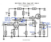
Post #1 phono preamp:
Schematic generally looks good, but . . .
Grid leak bias on the ECC88? How consistent is that from the triode on the left channel to the triode on the right channel? How consistent is that from one ECC88 to another ECC88? The maximum grid resistor is specified as 1 Meg Ohm, but the schematic shows 10 Meg Ohm. You may have to select ECC88 tubes to get good performance.
The ECC88 cathode is grounded. Don't you want a little self bias? Will the ECC88 distort on a loud section on a record if there is only grid leak bias?
Will the ECC88 have grid current on a loud section on a record? Once grid current starts, the bias will shift, because the coupling cap will come to a different charge (voltage across the cap). So the operating point of the ECC88 shifts according to signal level.
Instead, try to self bias the ECC88. If you do not like using a self bias resistor and bypass (electrolytic), use a film bypass cap. If you do not like that, use one or two signal diodes from the cathode to ground, to bias up the ECC88.
Unfortunately, that means you may want to change the ECC88 grid resistor to a lower value, and that reflects on the coupling cap and RIAA network. You probably could use a 1 Meg Ohm grid resistor, and self bias the cathode and have good and consistent performance. Then you can tube roll for sound, not tube roll just to make it work.
Make it as simple as possible, but no simpler - Albert EinsteinMake it as simple as possible, but no simpler - Albert Einstein
Last edited:
Thanks maaaan
")
Post #1 phono preamp:
Schematic generally looks good, but . . .
Grid leak bias on the ECC88? How consistent is that from the triode on the left channel to the triode on the right channel? How consistent is that from one ECC88 to another ECC88? The maximum grid resistor is specified as 1 Meg Ohm, but the schematic shows 10 Meg Ohm. You may have to select ECC88 tubes to get good performance.
The question of consistency arises in any RIAA preamp design without feedback and the EQ network as a coupling device. As the tube's internal plate resistance interacts with the network, how inert is it in terms of variations between different specimen of the same tube type? How inert is it in terms of tube ageing?
Best regards!
Great project!
Referring to the linestage section; I suppose that the output impedance even with the two sections in parallel, is quite high (3-4 kohm). Is the amplification factor approx. 20x?
Open-loop impedance is 3.4k but with feedback it drops to about 530
Two more questions regarding the linestage part:
1) What is the function of the 100k resistor just after the pot? Gridstopper, but at 100k?!
2) Are the tubes biased at 6v/6mA?
1 - It adds to the impedance of the volume pot for the feedback loop
2 - 6ma for the tube but 3mA per section with 3V on each cathode
1 - It adds to the impedance of the volume pot for the feedback loop
2 - 6ma for the tube but 3mA per section with 3V on each cathode
Thanks a lot for your reply! Looking forward to following this thread.
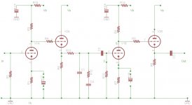
In my opinion one of the best way to make a tube phono is the one in attach.
This is a old project with 83 as gain and 82 as CF.
The gain is 40-41 dB without bypass until 46-47 with bypass.
With 12BZ7 it is working also fine
The reason is mainly the low impedance of riaa network; the gain stage is not loaded by the network.
Also you can change the gain ( with cap bypass) without any alteration of the response on equ.
The diagram of Kuei is not properly well dimensioned.
Walter
Attachments
- Status
- This old topic is closed. If you want to reopen this topic, contact a moderator using the "Report Post" button.
- Home
- Amplifiers
- Tubes / Valves
- Kuei Yang Wang Inspired Preamp