Hello all,
I build this pre-amp, as my first "comeback" to 35 years ago hobby. But I never touched tubes before ;-).
I connected the final assembled pre-amp product to my old Parasound HCA-750A and find out that it triggers Parasound "self-protect" if I'm run it in normal mode. If I reduce the input volume reducer under 15% it running find OK.
I already change the output resistor to 10K (that improves a bit stability) and now looking for additional improvement.
BTW: It sounds not too bad for a cheap Chinese kit.
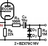
Add a couple of back-to-back zener diodes right at the output, like this (12V to 16V should be fine). They will clamp the voltage to a safe level, no need to compromise on bandwidth.I already change the output resistor to 10K (that improves a bit stability) and now looking for additional improvement.
Attachments
Changing the output resistor is not the best of ideas. In fact it is pretty stupid to load the tube device unneccessarily with 10 kOhm AND the following amplifier.
The issue is the high B+ voltage and slow ramp up time of tubes charging the output caps slowly thereby creating a rising voltage at the outputs that may damage the amplifier. Semi's don't like a few hundred Volts. We like 10 uF and we like 120 kOhm but they both enhance the issue.
There is a safe solution to solve this without detrimental effect. Even better the device will be way safer to other devices. Using a muting circuit as indicated in post #10 is one of the wisests decisions one can make in preamps/buffers. This was standard design practice for decades but seems to be forgotten. I dare to say all devices that don't have a muting circuit are potential woofer killers, certainly tube gear with long warm up times and high voltages. In another thread I read a power amplifier has a heavy power on/off thump and people seem to like this because the designer is famous?! Maybe a result of the world being too busy with corona?!
For those that worry about contacts in the signal path: short outputs via a resistor to GND and then release. That way they are NOT in the signal path. Make the delay a minute and use a circuit for instance with a red LED that blinks red when warming up and muting shorted to GND, changing to solid green when unmuted. Very intuitive and in use for many many years. No annoying plops and power on/off thumps. No prescribed/certain power on/off sequence Just plain good operating audio stuff.
Note: the 120 kOhm output resistors must stay so that there is a path for the output caps to charge. At this point a series resistor of 100 Ohm can be used followed by the relay contacts that short to GND.
Last edited:
Sometimes solutions are too simple. With a tiny output cap of 0.47 uF only high impedance loads of over 50 kOhm can be connected thereby forcing the user to adapt to an, in principle, unnecessary issue i.e. needing a suitable high input impedance amplifier that is used in a forced wedding with this specific preamp. Techs call this a "system choice". This while modern amplifiers tend to be 10 Kohm input impedance. People tend to forget such limitations and may connect a different low input impedance amplifier after a while without understanding the now introduced bass roll off that surely does not enhance the listening experience...
And with the 0.47 uF you still have the power on/off plops and possible 140V surge (only shorter but that does not make to much difference with semis!) at the inputs of that power amplifier. Also the power on/off sequenced still is prescribed/predefined so nothing is in fact solved. On the contrary, more issues were introduced. So this is a fake solution")
If one likes his woofers and safe operation with no annoying side effects just make use of a slow turn on/fast turn off muting circuit. Keep using the original 10 uF output caps and the 120 kOhm resistors and be relatively undependant of what power amplifier you may connect. Your woofers will like you even more as chances of bass roll off are unlikely.
* Why do many people object to well known solutions to annoying issues that can be solved without penalties? Is a simple muting circuit too difficult to understand/implement? No need for an extra transformer as the few mA the circuit draws can be taken from the filament voltage. Added cost is under 10 Euro.
And with the 0.47 uF you still have the power on/off plops and possible 140V surge (only shorter but that does not make to much difference with semis!) at the inputs of that power amplifier. Also the power on/off sequenced still is prescribed/predefined so nothing is in fact solved. On the contrary, more issues were introduced. So this is a fake solution
If one likes his woofers and safe operation with no annoying side effects just make use of a slow turn on/fast turn off muting circuit. Keep using the original 10 uF output caps and the 120 kOhm resistors and be relatively undependant of what power amplifier you may connect. Your woofers will like you even more as chances of bass roll off are unlikely.
* Why do many people object to well known solutions to annoying issues that can be solved without penalties? Is a simple muting circuit too difficult to understand/implement? No need for an extra transformer as the few mA the circuit draws can be taken from the filament voltage. Added cost is under 10 Euro.
Last edited:
We are discussing tube amps here, and they typicall has input impedanced inSometimes solutions are too simple. With a tiny output cap of 0.47 uF only high impedance loads of over 50 kOhm can be connected thereby forcing the user to adapt to an, in principle, unnecessary issue i.e. needing a suitable high input impedance amplifier that is used in a forced wedding with this specific preamp. Techs call this a "system choice". This while modern amplifiers tend to be 10 Kohm input impedance. People tend to forget such limitations and may connect a different low input impedance amplifier after a while without understanding the now introduced bass roll off that surely does not enhance the listening experience...
And with the 0.47 uF you still have the power on/off plops and possible 140V surge (only shorter but that does not make to much difference with semis!) at the inputs of that power amplifier. Also the power on/off sequenced still is prescribed/predefined so nothing is in fact solved. On the contrary, more issues were introduced. So this is a fake solution
If one likes his woofers and safe operation with no annoying side effects just make use of a slow turn on/fast turn off muting circuit. Keep using the original 10 uF output caps and the 120 kOhm resistors and be relatively undependant of what power amplifier you may connect. Your woofers will like you even more as chances of bass roll off are unlikely.
* Why do many people object to well known solutions to annoying issues that can be solved without penalties? Is a simple muting circuit too difficult to understand/implement? No need for an extra transformer as the few mA the circuit draws can be taken from the filament voltage. Added cost is under 10 Euro.
the hundreds of kohm.
The turnon/off glitches is ( has been ) solved by proper power
sequencing, power on pre first, after settling time power amp.
power of in reverse order, power amp first, allow to "bleed off" then pre
If one should drive an sandamp with 10k input impedance then something
is needed yes. But how common is that among this groups readers ?
Added cost is under 10 Euro.
Under 10 Euro and assembled already: Audio Speaker Protection Board DIY Components Kit for Stereo | eBay
Thanks to everyone responding so quickly.
I maybe was not clear as it looks as the problem in this case is not only during first power up and warm-up time. The issue is persistent all the time during the usage and not only in the first minutes.
What will be suggested approach to troubleshoot this ?
Thanks for a great feedback.
I maybe was not clear as it looks as the problem in this case is not only during first power up and warm-up time. The issue is persistent all the time during the usage and not only in the first minutes.
What will be suggested approach to troubleshoot this ?
Thanks for a great feedback.
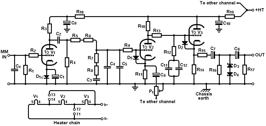
Sounds like cap leakage. You need to use a plastic capacitor, or use two electrolytics in series like this (C7, C8, R16, R17, D3, D4). The second cap (C8) can be a low-voltage type. e.g. 25V.Thanks to everyone responding so quickly.
The issue is persistent all the time during the usage and not only in the first minutes.
What will be suggested approach to troubleshoot this ?
Sorry but no. If you had read the full thread or at least the 4 or 5 posts above yours you would have learned that:We are discussing tube amps here, and they typicall has input impedanced in
the hundreds of kohm.
.........................
If one should drive an sandamp with 10k input impedance then something
is needed yes. But how common is that among this groups readers ?
has as much "sand" as you would find in an average beachParasound HCA-750A and find out that it triggers Parasound "self-protect"
Seems to me as a reasonable value.0.47uf into 100k gives frequency response rolloff of .5 db at 20hz
Most speakers don't sound at 20hz, and 0.5dB level shift is not detectable by human.
Using a smaller filmcap would totally eliminate the leakage of an electrolytic
cap, and some say that the sound of eletrolytic is bad.
Agreed it sounds like leakage...
FWIW, I use these as the output of my preamp to drive the power amps, one of which is 5k.
C4GADUC5100AA1J KEMET | Mouser Canada
FWIW, I use these as the output of my preamp to drive the power amps, one of which is 5k.
C4GADUC5100AA1J KEMET | Mouser Canada
What do you suppose the input impedance/resistance of a Parasound HCA-750A is?
Probably either 47k or maybe as low as 10k.
That will always be the load for this preamp, so when choosing the value of output coupling cap, that will need to be kept in mind.
The pulldown resistor on the output of the preamp and the input load resistor (or volume control) in the power amp will be in parallel, so even if the preamp pulldown resistor is 1M or something large like that, the power amp's input resistor will still set the load.
If Rload = 10k ohms and
If C = 0.47uF then
f3 = 34Hz
You'll want to make f3 about 5Hz at most, right? For f3 = 5Hz with a 10k ohm load, you'll need a 3uF output capacitor.
A 3.3uF 400V poly-whatever cap should be OK, right? They exist. Or parallel two 2.2uF 400V per channel. That would be close enough.
The MerlinB opposing zener idea looks like it should help here too.
Clamp that sucker!
--
PS - Just noticed that the preamp's B+ is at least +260V, and that output blocking cap is rated at 250V. That ain't good. The output cap should be rated 300V minimum.
Last edited:
I think ( that is my personal opinion) that 20hz is a good lower frequency.[/FONT]What do you suppose the input impedance/resistance of a Parasound HCA-750A is?
Probably either 47k or maybe as low as 10k.
That will always be the load for this preamp, so when choosing the value of output coupling cap, that will need to be kept in mind.
R1 and Rload will be in parallel, so even if R1 is 1M or something large like that, Rload will still set the load.Code:[FONT=Courier New] ---- C1 -----|-----------| | | R1 Rload | | | | ___________|__________| | GND [/FONT]
If Rload = 10k ohms and
If C = 0.47uF then
f3 = 34Hz
You'll want to make f3 about 5Hz at most, right? For f3 = 5Hz with a 10k ohm load, you'll need a 3uF output capacitor.
A 3.3uF 400V poly-whatever cap should be OK, right? They exist. Or parallel two 2.2uF 400V per channel. That would be close enough.
The MerlinB opposing zener idea looks like it should help here too.
Clamp that sucker!
--
This prevents subsonical noice from intermodulation the bass.
Close to none meda has 20 hz or lower recorded, no musical information
is lost by cutting at 20hz ( cutting at 35hz would only affect maybe 10%
of all recordings )
1uF film cap could be right in this case, cut at 16hz. 0.68uF will cut at 23hz
Last edited:
What do you suppose the input impedance/resistance of a Parasound HCA-750A is?
Probably either 47k or maybe as low as 10k.
That will always be the load for this preamp, so when choosing the value of output coupling cap, that will need to be kept in mind.
The pulldown resistor on the output of the preamp and the input load resistor (or volume control) in the power amp will be in parallel, so even if the preamp pulldown resistor is 1M or something large like that, the power amp's input resistor will still set the load.
If Rload = 10k ohms and
If C = 0.47uF then
f3 = 34Hz
You'll want to make f3 about 5Hz at most, right? For f3 = 5Hz with a 10k ohm load, you'll need a 3uF output capacitor.
A 3.3uF 400V poly-whatever cap should be OK, right? They exist. Or parallel two 2.2uF 400V per channel. That would be close enough.
The MerlinB opposing zener idea looks like it should help here too.
Clamp that sucker!
--
PS - Just noticed that the preamp's B+ is at least +260V, and that output blocking cap is rated at 250V. That ain't good. The output cap should be rated 300V minimum.
PECIFICATIONS
Continuous Power Output - Stereo:
75 watts RMS x 2, 20 Hz - 20 kHz, 8 Ω, both channels driven;
125 watts RMS x 2, 20 Hz - 20 kHz, 4 Ω, both channels driven
Continuous Power Output - Mono: 250 watts RMS, 20 Hz - 20 kHz, 8 Ω
Current Capacity: 20 amperes peak per channel
Slew Rate: > 130 V/盜econd
Power Bandwith: 5 Hz - 100 kHz, +0/-3 dB at 1 watt
Total Harmonic Distortion: < 0.06 % at full power; < 0.03 % typical levels
IM Distortion: < 0.04 %
TIM: unmeasurable
Dynamic Headroom: > 1.5 dB
Interchannel Crosstalk:
> 80 dB at 1 kHz;
> 63 dB at 20 kHz
Input Sensitivity:
0.775V for full output
Input Impedance: 33 k Ω
S/N Ratio:
> 110 dB, full power, input shorted, IHF A-weighted
Damping Factor: > 800 at 20 Hz
Power Consumption: 240 watts
- Status
- This old topic is closed. If you want to reopen this topic, contact a moderator using the "Report Post" button.
- Home
- Amplifiers
- Tubes / Valves
- output of valve preamp showing a high voltage when turned on