...I don't think there are many readers of this thread....
Well, you are trying to use "all 3 parts" of an obscure tube, when it could be done in one 6AU6.
And others are interjecting "what if??" without benefit of their insight.
Will it oscillate?
The slope network we can reject by inspection. Its phase shift is maximum when the amplitude response is steep. In this case, around 1KHz. At the ends it shelves-off and the phase shift returns to zero. If the forward amplifier has low error (amplitude or phase) to beyond the ends of the "slope", as it must do do what it should do, then it will not be troubled by the mild phase shift at mid-band.
The amplifier has three tubes but the NFB is only around two of them. If we don't do anything funny (added nodes) a 2-stage finite-gain amplifier will never oscillate.
Moreover you have a gain-stage and a buffer. They are of similar cathode construction and work on similar current. They will have similar cathode impedances. The gain-stage has gain because plate load is much larger than cathode impedance. For similar capacitance loading this also means its top roll-off will be much lower than the buffer's roll-off. Numerically: both stages have GBW near 10MHz. The gain stage gives Gv=100 so rolls-off at 100KHz. The buffer rolls-off at 10MHz. The gain-stage's gain WILL be down to unity before the buffer's gain begins to droop. At 10MHz the gain-stage is 90 deg and Gv=1, the buffer may be approaching 45deg and gain a bit less than unity.
This gives a unity-gain NFB response that is for-sure stable but shows a mild bump-up at ~~3MHz. The tilt network has little effect. The mystery 20pFd cap across one leg of the tilt network comes into play here. If it is larger and on the other side this becomes a 3rd pole and you *can* get unstable. As shown it tends to counteract any wiring capacitance wiper-to-ground and some dozens of pFd is appropriate.
Output loading....
Well, are you gonna leave the output hanging? Or connect it to something? To what? Older Hi-Fi might be 100K or more, and that probably makes no difference. Modern Hi-Fi often runs 10K, which is significant to tubes.
And unless it will be in-box with the next stage, you always have cable capacitance. 100pFd per meter. So 100pFd-1,000pFd in domestic work.
WHY do you have a cathode follower on the end? It is debatable, but the habitual reason we do this is SO that loading is unimportant. We make the source << load and forget about it. This triode's cathode impedance may be 250 Ohms. Loads to 25K make "no difference" (<1%). Loads to 2k5 make "small difference", 10%. As we rarely go as low as 2k5, a cathode follower is a good safe bet for domestic Hi-Fi.
1,000pFd on 250 Ohm source makes a pole at 600KHz. Yes, this starts to eat into our phase margin. We do not need 600KHz of audio signal. A good path is to give the amplifier "two outputs". One direct from the buffer back to the NFB network. A second, with 500r-1K series resistor, drives the external load. We can hang great shorts on the 500r build-out resistor and still have 2/3rd of design gain through the NFB network. Phase-shift inside NFB is likewise reduced.
Going back to basics: if you run that pentode at 25k load it can drive the tilt-network and a 100K load fine. Especially if you scale the network up by a factor of say 5X (250K pot, 1nF caps, 250k and 90k resistors). The network becomes at-least 66k, which a 25k plate can handle well. Especially since forward gain is near 100, closed gain only 2, 50:1 of NFB working in our favor. So a single 6AU6 can work, at 1/3rd the power consumption (and ripple filtering cost). And leave the 6M11 on the shelf.
I'm not sure what the question of "line level" is. Given 300V supply you should be able to swing 60V peak. Naked, the THD would be 5%, but we have 50:1 NFB so it will be ~~0.1% THD. This 60Vpk comes from 25K source, so if heavily loaded with 10K we only get 17V peak 12V rms. The more logical place to put an EQ is after the Volume knob and probably at the level of the Power Amp. Few Hi-Fi power amps take even 2.8V rms to smack full power output, so we have 4X more clipping level than we should need.
Last edited:
PRR-
Thanks for the input -unfortunately there's no 'Google translate for electronics dummies' so many of your comments are 'way over my head'.
")
I was just trying to build a circuit that I assumed was going to work, since it had been 'published'.
I thought it would be fun. It's only a few dollars in tubes and components and has provided 'endless amusement' for the past little while.
Anyway, thanks for your research and thoughts on this; I do appreciate the time it must have taken.
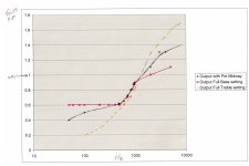
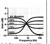
I was really looking for a simple fun project to demonstrate how a tilt control worked..see the attached graph.
This 6M11 project is very far from that...and it looks like it's not a good 'vehicle for learning' for a beginner, either.
Thanks for the input -unfortunately there's no 'Google translate for electronics dummies' so many of your comments are 'way over my head'.
Well, you are trying to use
Moreover you have a gain-stage and a buffer.
Really, it has nothing to do with me.WHY do you have a cathode follower on the end?
I was just trying to build a circuit that I assumed was going to work, since it had been 'published'.
I thought it would be fun. It's only a few dollars in tubes and components and has provided 'endless amusement'
for the past little while.I read that 'the tilt circuit is best driven into and from cathode follower circuits' so the multi-stage approach in SY's schematic seemed to fit that.So a single 6AU6 can work, at 1/3rd the power consumption (and ripple filtering cost). And leave the 6M11 on the shelf.
I thought I'd read that volume and tone controls should be separated by a 'gain' section, so the approach in this schematic with the tilt control in the section after the volume fit that recommendation.The more logical place to put an EQ is after the Volume knob
Tone control in a power amp section would be different for sure.and probably at the level of the Power Amp.
Anyway, thanks for your research and thoughts on this; I do appreciate the time it must have taken.
I was really looking for a simple fun project to demonstrate how a tilt control worked..see the attached graph.
This 6M11 project is very far from that...and it looks like it's not a good 'vehicle for learning' for a beginner, either.
Attachments
Yes, I have; thanks.
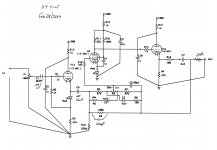
I've also read the 'Tilt' sections in Blencowe's HiFi Tube Preamp book but none of those examples has the NFB running 'around' the filter, which adds an extra complication for my understanding.
Anyway, I have a good long project list to work on, and I haven't cut chassis metal for the compactron sockets, so I can happily walk away from this one if necessary.
Last edited:
Ah, maybe it would help to say that the example in post #45 is *exactly* what's been proposed. Thinking in op-amps is tremendously useful; I'd even say a required skill. An anode-follower stage is really just a somewhat imperfect inverting op-amp.Yes, I have; thanks.
I've also read the 'Tilt' sections in Blencowe's HiFi Tube Preamp book but none of those examples has the NFB running 'around' the filter, which adds an extra complication for my understanding.
No need for purists to get all bent out of round - the first op-amps were made with vacuum valves, even before miniature button base valves, so no cardinal sins are involved.
All good fortune,
Chris
Of the several tilt examples in the Broskie article you must be referring to the Quad example?Ah, maybe it would help to say that the example in post #45 is *exactly* what's been proposed.
Also...?'what's been proposed'??...
I don't understand, really. The only proposals I've read have been some suggestions from Osvaldo (increase the C6 value, collect some gain data).
I had a couple of goals in starting this little project- playing with opamps and solid state circuits certainly wasn't one of them!
I've done that a bit and didn't find it very interesting or rewarding.
It's a good learning experience - a supposed 'working schematic' that doesn't (for me), and nobody really seems to be able to figure out why.
I guess I should have said "what you proposed", a unity gain buffer and an anode follower with internal output buffer. In op-amp terms, a unity gain buffer and an inverting amplifier stage with non-inverting input to ground, as shown in the referenced article in #45.
There's nothing fatally wrong with your schematic, so the problem must be in the implementation. Nobody can figure that out remotely.
Chris
There's nothing fatally wrong with your schematic, so the problem must be in the implementation. Nobody can figure that out remotely.
Chris
- Status
- This old topic is closed. If you want to reopen this topic, contact a moderator using the "Report Post" button.
- Home
- Amplifiers
- Tubes / Valves
- 6M11 Compactron Preamp with Tilt Tone Control