I managed to find a schematic of a similar power supply used in another Hammond organ amplifier. Of course most of those power outputs have been removed on my amp.
If the amp has been used regularly, you may be able to keep using the old power supply filter capacitors - but I wouldn't bet on it.
I think you'll find that the terminals on the can caps are used as circuit connection points. If you switch to axial (or -ugh- radial) capacitors you'll probably need new connection points, so you may need some more solder terminal (lug) strips. You can get new can-style caps but they tend to be expensive.
Your idea of tracing the existing circuit and drawing the schematic is a good one.
If you could do a sim, that'd be great! Thanks! It'll probably make more sense once I see your sim, but the Hammond chokes won't provide the resistance of R354 and R355 that they'll be replacing. So substituting the chokes should provide the required voltage at the 275V tap for the power tubes? 310 volts should work for the power tube B+, then the 27k resistor will be used to set the preamp tube B+ correct?I'll do a quick sim and post it shortly based upon using the El Mighty Cacahuate amp.
If the amp has been used regularly, you may be able to keep using the old power supply filter capacitors - but I wouldn't bet on it.
I'm surprised the amp hasn't caught fire from the filter caps that are in it now, I think the amp has sat for most of its life and the electrolytic fluid has probably dried up. I see some amps using new vintage style can caps, but I'm not a fan of them.
Tracing the circuit should help me with translating schematics into wiring and vice versa. That wtfamps website has been helpful in explaining that as well.
Your idea of tracing the existing circuit and drawing the schematic is a good one.
+1
It will help you understand how it works and provide some valuable information to us so we can help you with it. If the schematic you provided for the power supply is correct, it seems unlikely that the power transformer is 300-0-300 Volts. I tried simming it, and the voltages are higher in the simmed circuit when using 300-0-300 Volts for the transformer. It seems the transformer is more likely to be around 265-0-265 Volts.
With plenty of downstream filtering like that you can easily adjust the output DC voltage by varying the value of the first C. Too much voltage, use a smaller input capacitor; not enough, use some more. You're unlikely to get into the range of too much capacitance (so: too high peak current for the rectifier) with modern line voltages. An elegant solution here (shades of the Marantz model 5, and lots of DIY amps, without commercial cost constaints) is to make the input capacitor from a motor run polypropylene can cap. Lasts forever-ish. It really wouldn't hurt to have new power supply caps anyway.My only challenge is trying to adapt my power transformer and tube rectifier to a CLCLC filter as you've described. I'm still trying to find the specs on the power transformer in my amp. I'm pretty sure the secondary is 300v-0v-300v, with a single 6v heater winding as well.
All good fortune,
Chris
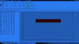
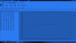
Here are two sims. The first is an attempt to mimic the schematic that you attached, and the second is a sim for the Cacahuate circuit. Both assume a power transformer of 265-0-265 Volts.
For the Cacahuate circuit, The B+ for the power tubes at C3 is 314.81 Volts at 6.468 mV of ripple. The B+ for the 6CG7 at C4 is 302.3 Volts at .28592 mV. I am assuming the use of two 156R Hammond chokes.
If, as I suspect, your power transformer has 250-0-250 Volts, you can omit the first 68 Ohm resistor for very similar voltages in the Cacahuate circuit.
Attachments
Thanks all for the kind comments. I'm glad the Cacahuate write-up is useful for others!
FWIW I measured 315V B+ when built with the 5U4. This was more or less exactly as simmed in PSUDII. The EZ81 is a more practical rectifier for a stereo EL84 SE circuit and it keeps everything 9 pin and cuts costs a bit. Probably why you see that pairing in organ/console amps more frequently. I wouldn't hesitate to use it in this application.
With two stages of filtering, the 156R will still do a good job here. I'm getting -70db by plugging it into a spreadsheet calculator. The original amp was built to play with a pair of Cornwalls so I went for maximum filtering. PSRR is ok for the 6CG7 input stage (another -15db ish), so I think you'd be AOK. PSUDII seems to think so too, according to tizman.
I wouldn't obsess too much over the B+. If I built and measured anything between 300V and 320V, I probably wouldn't worry about making any adjustments. There are some EL84 variants like EL84M that supposedly have higher anode Vmax ratings, if your B+ ends up high and it bothers you.
Chris:You're unlikely to get into the range of too much capacitance (so: too high peak current for the rectifier) with modern line voltages.
I don't understand this idea. How does the slightly higher line voltage nowadays (with slightly higher HV on the power transformer secondary) affect the current charging the first filter capacitor?
I'm always interested in learning, so a link or explanation would be appreciated.
I'm usually pretty careful to watch the 'max' cap suggestions in the tube datasheets; rectifier tubes can be expensive.
Thanks all for the kind comments. I'm glad the Cacahuate write-up is useful for others!
The write up is excellent and serious (DIY) community service IMO. When I read it a while back, it was after reading several other guides on amp design, and it made everything very clear to me. I have recommended it to noobs (like myself) several times since then. Well done!
I have been using Russian NOS 6P14P-EV tubes lately. They are a reasonably priced equivalent to the EL84M with a maximum anode voltage of 400 Volts. They cost about the same as new production EL84s and are very sturdy and well built. Using these tubes allows for higher B+ voltages and for the use of power transformers that might not be ideal for regular EL84s, something that is very helpful when building amps using salvaged power transformers. These tubes would allow for the amp to be built without having to drop the voltage with more resistance in the power supply even if the transformer is in fact 300-0-300 Volts.
A schematic with voltages based on tracing out the circuit, as it is, would be very helpful. As I mentioned earlier, I suspect that the PT is at around 250-0-250 Volts based on the voltages shown by the power supply schematic posted by the OP.
I just want to leave the hobby with more useful information than when I found it") It makes me really happy to know that my lighthearted approach brings clarity to others trying to get into DIY.
It makes me really happy to know that my lighthearted approach brings clarity to others trying to get into DIY.
I've been meaning to give the 6P14P and 6P15P a try. Just waiting for the next order of tubes (that I want but don't have an immediate use for) from overseas. I'm hoping to document a EL84 push pull build as a kind of cousin to the Cacahuate this year.
It makes me really happy to know that my lighthearted approach brings clarity to others trying to get into DIY. I've been meaning to give the 6P14P and 6P15P a try. Just waiting for the next order of tubes (that I want but don't have an immediate use for) from overseas. I'm hoping to document a EL84 push pull build as a kind of cousin to the Cacahuate this year.
The old Hammond organs are very conservatively designed. They were meant to be reliable with daily use and being on for hours. So, no worries with the PT. One of my personal favorite low power amp is the SE el84 driven by a 12a?7 type. That combo seems to yield excellent audio whether it is a RH, or Maggy or RCA or similar circuit. Putting extra effort into designing the Power supply seems to be very important in getting the best sound. Using film caps like Solen or ASC or Panasonic DC link, makes the amp sound more dynamic. Your chassis seems roomy enough to accomodate film caps in the PS. With the RH type amp, if you use a preamp, the input sensitivity is not an issue.Hi everyone,
I'd like some advice on the feasibility of converting a mono Push-Pull amp to a Single ended stereo amp. What I have is an old Hammond-Everett PP EL84 amplifier that's been converted to a guitar amp.
Is anyone aware of stereo amp circuits using EL84's and 12AX7's in a single ended configuration?
Thanks in advance!
I just had another look at my sim, and realized that by trying to show the ripple in the chart by using a one second sample, I missed that the sim exceeds the IFRM of the 6CA4 on initial startup of the circuit. I'm not sure if this is really an actual concern, as the 6CA4 warms up slowly. Please let me know if this is an actual concern as I am having a hard time finding info on it online. I have used SS rectifiers in the past that largely avoid this problem
Putting extra effort into designing the Power supply seems to be very important in getting the best sound.
100% correct! The PSU is the foundation upon which the entire amp is erected. It is not possible to build a good amp without having a competent PSU.
Especially when SS rectification is employed and fairly frequently when vacuum rectification is employed, using a film cap. in the 1st filter position is a "frill". Unlike the reservoir cap., the 1st cap. is not in the signal path and modern low ESR 'lytics can challenge film performance, while being much more volumetrically efficient. A significant financial incentive also favors an electrolytic 1st filter capacitor. The OP mentioned a 6CA4/EZ81 rectifier. This part will be more than adequate in the 1st filter position. Notice the 105o C., long life, and high ripple current ratings.
Last edited:
Chris:
I don't understand this idea. How does the slightly higher line voltage nowadays (with slightly higher HV on the power transformer secondary) affect the current charging the first filter capacitor?
I'm always interested in learning, so a link or explanation would be appreciated.
I'm usually pretty careful to watch the 'max' cap suggestions in the tube datasheets; rectifier tubes can be expensive.
It's just that higher transformer voltages require smaller first capacitors, thus lower peak currents, for a given DC voltage goal. The limiting condition is when the transformer voltages are so high that *no* capacitor is needed, and we have a "choke input" power supply, and the lowest possible rectifier peak currents.
All good fortune,
Chris
You're unlikely to get into the range of too much capacitance (so: too high peak current for the rectifier) with modern line voltages.
It's just that higher transformer voltages require smaller first capacitors, thus lower peak currents, for a given DC voltage goal.
It sounded to me that you were saying that any (large) value capacitor in the first spot would be OK.
I think some folks have damaged rectifier tubes by putting 'too high capacitance' caps in that first position, which would explain the tube datasheets specifying the max capacitor size for a cap input filter.
http://tdsl.duncanamps.com/pdf/ez81.pdf
Also, I don't see that the first cap value has a big effect on the 'average' DC voltage, just the ripple (I did a bunch of PSUD sims..). So adjusting the B+ with the cap value isn't something I'd try.
Also, I don't see that the first cap value has a big effect on the 'average' DC voltage, just the ripple (I did a bunch of PSUD sims..). So adjusting the B+ with the cap value isn't something I'd try.
Within the context of the OP's desire to use his original power transformer, maintaining the original DC voltage at higher AC voltages means something needs adjusting. A smaller input capacitor is an easy price to pay. If the OP doesn't wish to trust modeling and doesn't want to breadboard it first, several capacitors making several likely steps possible can be mounted, maybe a 16uF, a couple of 8uF's and a 4uF can be mounted and unneeded caps connected downstream. Or whatever nice motor-run caps are laying about, if chassis space allows.
All good fortune,
Chris
Motor run caps. are BIG. DC link parts may be a less space consuming alternative. Remember, motor run parts have to take the stress of constantly applied AC. A part in a PSU filter does not experience that sort of stress.
The 6CA4/EZ81 data sheet shows 50 μF. as the max. 1st cap. value. The 47 μF./400 WVDC part I previously linked is exactly what's needed, in the 1st position. Don't stress the vacuum rectifier. Don't consume space needlessly. Don't spend more than necessary to get the job done well.
The 6CA4/EZ81 data sheet shows 50 μF. as the max. 1st cap. value. The 47 μF./400 WVDC part I previously linked is exactly what's needed, in the 1st position. Don't stress the vacuum rectifier. Don't consume space needlessly. Don't spend more than necessary to get the job done well.
Here are two sims. The first is an attempt to mimic the schematic that you attached, and the second is a sim for the Cacahuate circuit. Both assume a power transformer of 265-0-265 Volts.
A-Ha! Now I understand more clearly what needs to be done to the power supply. Hopefully I can trace a schematic in the next couple days, then it should be straightforward to modify your sim if needed by my findings.
Thanks all for the kind comments. I'm glad the Cacahuate write-up is useful for others!
FWIW I measured 315V B+ when built with the 5U4. This was more or less exactly as simmed in PSUDII. The EZ81 is a more practical rectifier for a stereo EL84 SE circuit and it keeps everything 9 pin and cuts costs a bit. Probably why you see that pairing in organ/console amps more frequently. I wouldn't hesitate to use it in this application.
Wow! The man himself! I feel very lucky to have found your website, it has cleared up several misunderstandings I had about vacuum tube circuits. It is definitely a godsend for toob noobs like me!
Good to know that my EZ81/6CA4 power supply should work for the Cachuate circuit. A triode/UL stereo amp circuit is exactly what I wanted to use in this conversion.
The old Hammond organs are very conservatively designed. They were meant to be reliable with daily use and being on for hours. So, no worries with the PT. One of my personal favorite low power amp is the SE el84 driven by a 12a?7 type. That combo seems to yield excellent audio whether it is a RH, or Maggy or RCA or similar circuit. Putting extra effort into designing the Power supply seems to be very important in getting the best sound. Using film caps like Solen or ASC or Panasonic DC link, makes the amp sound more dynamic. Your chassis seems roomy enough to accomodate film caps in the PS. With the RH type amp, if you use a preamp, the input sensitivity is not an issue.
The RH amp does look like a good option, but unfortunately I don't have a tube pre-amp (yet). Looks like the Cacahuate circuit mentioned above is the one for me. Should be easy enough to source a 6CG7 and it still uses the same tube socket as the 12AX7.
For sure I will be using relatively high quality film caps with the power supply. That's the one area I don't want to be cheap with.
Motor run caps. are BIG. DC link parts may be a less space consuming alternative. Remember, motor run parts have to take the stress of constantly applied AC. A part in a PSU filter does not experience that sort of stress.
The 6CA4/EZ81 data sheet shows 50 μF. as the max. 1st cap. value. The 47 μF./400 WVDC part I previously linked is exactly what's needed, in the 1st position. Don't stress the vacuum rectifier. Don't consume space needlessly. Don't spend more than necessary to get the job done well.
Good point, I don't wan to over-do it, but I also don't want to under-do it either. Interestingly, I believe the first cap in the power supply circuit is a 50 μf capacitor, so the original design pushes the limits of the 6CA4. It's that big brown cap beside the rectifier tube and power transformer in the pics from my first post.
I just had a quick look at those pics. One thing I noticed that you should put near the top of your 'todo' list (IMO) is to take the green wire from the power cord, attach a ring lug to the end, and then bolt it to the chassis with a good star washer digging into the chassis.... in the pics from my first post.
Making the connection between 'circuit ground' and 'chassis safety ground' can be discussed later.
You have a great project on the go. I do agree with the comments that film caps or motor run caps aren't necessary in the power supply filter- good electrolytics like the type that Eli suggested will do the job just fine, cost less and take up a lot less space. IMO of course.
Yes, grounding the chassis is something I'll do even if I don't convert the amp itself (though with all the help I've gotten here, its looking pretty likely at this point).
I'll take a look at the price difference between film and electrolytic caps. Seeing as this is my first amp build, it probably won't be worth all the extra money for film caps. They can be upgraded later anyways.
I'll take a look at the price difference between film and electrolytic caps. Seeing as this is my first amp build, it probably won't be worth all the extra money for film caps. They can be upgraded later anyways.
- Status
- This old topic is closed. If you want to reopen this topic, contact a moderator using the "Report Post" button.
- Home
- Amplifiers
- Tubes / Valves
- Convert PP Mono amp to SE stereo