Chris Hornbeck: Thanks for the reply, and no need to apologize. I asked because it hasn't been on my radar at all until you mentioned it. When you say "With a good solid 50 Hy or more (with current) primary", to what are you referring? The output transformer? Sorry if this is a dumb question, I'm a noob in most respects....
Hi fellow nightowl. Yes, the output transformer's primary inductance appears as a parasitic inductor in parallel with the "ideal" transformer itself, so forms a high-pass filter with the output valve's "plate resistance" in parallel with the reflected load impedance. Unavoidable, but worse for an amplifier with loop feedback because the inductance varies significantly with signal level, so shifting a significant contribution to the open loop magnitude and phase response with signal level.
Messy stuff and fortunately not so much an issue with an open loop amplifier. I suspect that this factor is about 90% of the current popularity of SET's. It's just harder to get them wrong. And almost everybody gets loop feedback amplifiers somewhat wrong.
But even an open loop amplifier gets challenged by the falling and reactive load that the parasitic inductor makes at lower frequencies. That's life in the fast lane, but we can minimize the output valve's stress by rolling off any low frequencies that we can't use anyway. All engineering is made of compromises.
All good fortune,
Chris
I finally got a rough circuit diagram of my power supply drawn up. The only thing I couldn't show was the center taps on the secondary winding of the power transformer, but they both go to ground. The lead from R4 has been clipped off, so it doesn't do anything. I'm still figuring out which sections of the power supply feed which components.
Attachments
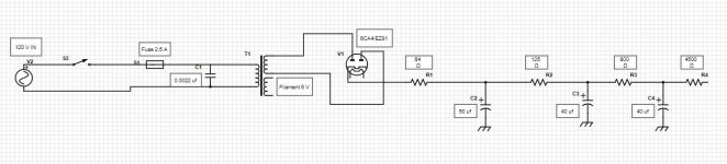
C3 feeding the O/P tube plates makes sense.
You could eliminate R1 and replace R2 with a choke rated for at least 150 mA. The choke provides isolation from the remainder of the PSU, for the 6CA4. That isolation allows safe increase in the value of C3, the reservoir capacitor. I'm suggesting a "textbook" CLC filter.
You could eliminate R1 and replace R2 with a choke rated for at least 150 mA. The choke provides isolation from the remainder of the PSU, for the 6CA4. That isolation allows safe increase in the value of C3, the reservoir capacitor. I'm suggesting a "textbook" CLC filter.
C3 feeding the O/P tube plates makes sense.
You could eliminate R1 and replace R2 with a choke rated for at least 150 mA. The choke provides isolation from the remainder of the PSU, for the 6CA4. That isolation allows safe increase in the value of C3, the reservoir capacitor. I'm suggesting a "textbook" CLC filter.
Thanks Eli, would a CLCLC filter be worth the effort? The Cacahuate circuit I'm considering uses such a filter, and should reduce the DC ripple to effectively nothing.
While performance of CLCLC should be outstanding, the factors of cost, space, and weight all argue against the topology. JMO, the high performance 'lytic and C-14X choke previously suggested will fine, in combination with a well chosen reservoir capacitor. The ripple level will be satisfactorily low. This DC link cap. looks good to me. If the cost of that part is too high for your budget, this 'lytic will come reasonably close in performance.
The Triad C-14X is inexpensive and easy to source from Mouser. C-14X Triad Magnetics | Mouser This would work fine in place of R2. R3 likely has a voltage dropping function for the input stages in the original amp circuit, with the output stage taking power at the junction of C3.
Heh - sorry if I'm echoing earlier posts.
Some excellent gear uses electrolytic capacitors for power supply filtering. This type of capacitor was invented specifically for power supply filtering, providing large values in small packages at reasonable cost. Plastic power supply caps are not where I would spend my money first.
Last edited:
While performance of CLCLC should be outstanding, the factors of cost, space, and weight all argue against the topology. JMO, the high performance 'lytic and C-14X choke previously suggested will fine, in combination with a well chosen reservoir capacitor. The ripple level will be satisfactorily low. This DC link cap. looks good to me. If the cost of that part is too high for your budget, this 'lytic will come reasonably close in performance.
So if I understand correctly, R1 and C2 should be replaced with components of the same value, while R2 should be replaced by the C14X inductor of 6 H inductance, 150 ohm resistance and C3 should be replaced with a 100 uf cap. Then B+ power for the EL84's can be taken from the junction of R2 and C3.
Just need to make sure I've got all my bases covered!
The Triad C-14X is inexpensive and easy to source from Mouser. C-14X Triad Magnetics | Mouser This would work fine in place of R2. R3 likely has a voltage dropping function for the input stages in the original amp circuit, with the output stage taking power at the junction of C3.
Heh - sorry if I'm echoing earlier posts.
Some excellent gear uses electrolytic capacitors for power supply filtering. This type of capacitor was invented specifically for power supply filtering, providing large values in small packages at reasonable cost. Plastic power supply caps are not where I would spend my money first.
No worries about echoing earlier posts, it helps me to decide which are the best components!
")
Hi Jenghis -
You understand that your power supply design is dictated by the amplifier design that you choose? The values of the components at these locations (R1, C1, etc.) will change the voltage and degree of filtering that the power supply will provide. Pretty sure that a push-pull output will require less AC ripple suppression than a single ended design will. Your notion of CLCLC may be appropriate for a 6BQ5 single ended triode-mode output. If it were me, I would make my best effort at an initial design that includes both the power supply and the amplifier. You will want to remove those electrolytic can capacitors and replace them with new, modern electrolytic caps. Old electrolytic capacitors should be junked. Snap-in or computer types are available that will fit in the original location of the can caps, and be held by clamps that you can add. I'd also point out that you have a lot of space on that chassis, if you eliminate the tone controls. What do you want the resulting amp to do? Volume and tone control is often (usually) separated from the amplifier and put in a dedicated preamp. Again, my apologies if this was all covered in previous posts.
You understand that your power supply design is dictated by the amplifier design that you choose? The values of the components at these locations (R1, C1, etc.) will change the voltage and degree of filtering that the power supply will provide. Pretty sure that a push-pull output will require less AC ripple suppression than a single ended design will. Your notion of CLCLC may be appropriate for a 6BQ5 single ended triode-mode output. If it were me, I would make my best effort at an initial design that includes both the power supply and the amplifier. You will want to remove those electrolytic can capacitors and replace them with new, modern electrolytic caps. Old electrolytic capacitors should be junked. Snap-in or computer types are available that will fit in the original location of the can caps, and be held by clamps that you can add. I'd also point out that you have a lot of space on that chassis, if you eliminate the tone controls. What do you want the resulting amp to do? Volume and tone control is often (usually) separated from the amplifier and put in a dedicated preamp. Again, my apologies if this was all covered in previous posts.
Last edited:
Hi Jenghis -
You understand that your power supply design is dictated by the amplifier design that you choose? The values of the components at these locations (R1, C1, etc.) will change the voltage and degree of filtering that the power supply will provide. Pretty sure that a push-pull output will require less AC ripple suppression than a single ended design will. Your notion of CLCLC may be appropriate for a 6BQ5 single ended triode-mode output. If it were me, I would make my best effort at an initial design that includes both the power supply and the amplifier. You will want to remove those electrolytic can capacitors and replace them with new, modern electrolytic caps. Old electrolytic capacitors should be junked. Snap-in or computer types are available that will fit in the original location of the can caps, and be held by clamps that you can add. I'd also point out that you have a lot of space on that chassis, if you eliminate the tone controls. What do you want the resulting amp to do? Volume and tone control is often (usually) separated from the amplifier and put in a dedicated preamp. Again, my apologies if this was all covered in previous posts.
Yes, I'm redesigning the power supply so that it will work with the "El Mighty Cacahuate" amplifier circuit linked by tizman earlier in the thread. It is a single ended triode EL84 amp. That design calls for a plate voltage of approximately 310 V for the power tubes. My biggest challenge has been finding specs for the power transformer so I can verify the voltage output of the secondary winding. I may have to measure it to know for sure.
Those old can capacitors are pretty scary, they'll be the first thing to go. The old resistors don't look too great either. I might keep the "master" volume control between the input and output stages, but other than that, the amp doesn't need any pots.
Hi - If you have an amp design, figure out roughly what current the amplifier will draw for the output and driver stages, and get some cheap power resistors that will mimic that load. This is a simple Ohm's law calculation. Guess at what the amp will look like to the power supply, wire it up and see what voltage you get. Tube amps do not require exact voltages, so just get close to what your amp schematic specifies. It'll work if you are in the voltage neighborhood, then you can tweak to get closer. Hth!
- Status
- This old topic is closed. If you want to reopen this topic, contact a moderator using the "Report Post" button.
- Home
- Amplifiers
- Tubes / Valves
- Convert PP Mono amp to SE stereo