Correct, 75 Ohms would drop 3V at 40 mA. and be more suitable. A pair of resistors is used to reduce the wattage lost in each?
I sized the thermistors from this link.
http://www.vacuumtubeera.net/HalfWave-DoublerPowerSupplySystems.pdf
However I observe very few doublers using plate resistors so perhaps this is not really required?
I really need to find the link to heater voltage!
But I inadvertently mislead you by referring to heater failure.
I recall plots of tube emission which showed a rapid break-in period and loss of initial emission, followed by a plateau of consistent performance, followed by gradual failure (all at rated voltage). At reduced voltage the break-in was eliminated and emission was stable indefinitely making the tube a capital investment! The author argued that while emission levels were somewhat lower at lower heater voltages, the stability justified the compromise.
The string started with the RIAA preamp, but I also need to repackage my OTL headphone amp (AC too close to DC, and even with DC heaters there is a bit of 60Hz hum). So I was thinking of using this power supply for my headphones, as a remote power supply.
I am using 25E6 tubes for the headphones so I already have a 24V inverter for the heaters to be shared with the 25Z5.
The headphones only pull 30 mA. so the glow tubes should still be OK.
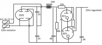
And the 25Z5 is intended for use as a doubler.
I am using 25E6 tubes for the headphones so I already have a 24V inverter for the heaters to be shared with the 25Z5.
The headphones only pull 30 mA. so the glow tubes should still be OK.
And the 25Z5 is intended for use as a doubler.
Attachments
> thinking of using this power supply
I see maybe 300V of raw DC, 22k, then 255V of gas. So 45V dropped in 22k, say 2mA.
IIRC the minimum keep-alive current in these gassers is 5mA. So it won't glow reliably.
That's no-load. With ANY load the gas-tube current is less.
With raw DC just 17% higher than gas-voltage, *any* small wobble in wall-voltage makes large change in gas current.
Headphone driver is likely to suck 20+mA, cause "440V" drop in 22k, something wrong here.
Of course there is something wrong! The student is not yet the sensai, if that is wrong.
I viewed the worst case as infinite load resistance so the "22k resistor" was both to prevent excessive current through the regulators, and sustain the minimum.
With infinite load all of the current would be determined by the 22k which would provide 13 mA., sustaining the minimum.
If the load is pulling 30 mA. at 300V the load must be 10k. The 22k resistor is in parallel to that so with about twice the resistance of the load it must pull about half the current? If so that is still within limits?
But the output of the 25Z5 will drop from 300V to about 265V at load, which seem precarious.
I guess the 0D3 could be combined with the 0B3 reducing the regulated 255V to 240v providing a bit more headroom.
In any case, I rely on the guidance of the sensai !
> I rely on the guidance of the sensai !
Zeners and gas-tubes in practical systems should be fed *twice* their nominal voltage, so you have a large resistor to absorb line and load variations.
So if you have 265V, you want to regulate near 132V. A Zener "might" be fine at 150V in a stable home. A gas tube needs ample excess (especially now that they have aged and the radioactivity dimmed) and I'd go 105V or maybe 140V.
And frankly, if I had 265V of raw DC, I'd just R-C-filter the heck out of it and use it in the preamp (done that lots of times). I don't see any need for regulating small tube audio. The more voltage the merrier.
Look at this 0B2 datasheet. Notice that it can take up to 210 V. to get the tube to "strike", when it's in total darkness. OTOH, when it's illuminated to a certain level, a max. of 127 V. will cause striking.
IMO, it's pretty obvious that gas discharge regulator tubes need to be out in the available light and not tucked away for some perceived cosmetic reason.
Some gas regulator specimens were manufactured with radioactive material inside to allow for reliable "striking" in the dark, which is an obvious military need. Synthetic nickel 63, which transmutes to copper via beta decay and has a 1/2 life of 101 years is an obvious choice for the radioactive material. Less than 1/2 of that stuff would have decayed, since the tubes were manufactured. This datasheet suggests that no radiation would escape an intact glass envelope. Dangerous gamma ray radiation is not mentioned.
Well, I had to try it...
As several of you predicted the 0D3 in combination with 0C3 did not strike.
An OD3 with 0B3 did strike providing 230V, but the 0B3 did not glow (has anyone observed that before?)
The 0D3 with an 0A3 strike providing 218V .
A pair of 0C3s strike about half of the time, even though the voltage is lower at 210V.
An 0C3 with 0B3 did not strike, even though voltage is yet lower at 195V. Seemed strange so I subbed another 0B3 and the pair struck every time! (and now the 0B3 is glowing)
An 0C3 with 0A3 strike every time at 180V.
All combinations of 0B3 and 0A3 strike, providing 180V, 165V, or 150V.
In summary, there is a lot of variation in the tubes (no surprise).
My 0D3 tubes seem to start easier than the others. A return to the data sheet may have anticipated this. Tung-Sol lists anode voltage, starting voltage, and operating voltage. The anode voltage is always about 30-35V above operating voltage, but starting voltage varies from 25V above operation to 10V above (for the 0D3).
Test results were the same in the dark, so I guess I must have stumbled across some radioactive tubes!
I was happy that I could find a combination supporting 230V, but as previously pointed out, there is no functional advantage over 265V and a R-C filter, it just looks cool!
PS I had forgotten than one of you suggested a 1 meg resistor in parallel with one of the tubes so that they could start sequentially, and all of the firing voltage headroom would be applied to one tube at a time. I added the resistor and:
Now the 0D3 and 0C3 strike, providing 240V, but not the 255V expected, and neither of the tubes glow.
The pair of 0C3 tubes which previously started intermittently now start every time.
Now the 0D3 and 0C3 strike, providing 240V, but not the 255V expected, and neither of the tubes glow.
The pair of 0C3 tubes which previously started intermittently now start every time.
I have not checked yet.
I used a dummy load of 1 meg so almost no current to load.
Ideally I would have used a different resistor for each intended voltage, but I used a single compromised value.
I am not in the "studio" now, but can substitute more realistic loads tonight. (a friend told me to refer to my workshop as an artist's studio, and I might get more tolerance of the mess!)
They need a minimum of 5ma to regulate...
You can use a Zener calculator to find the correct dropping resistor.
Zener Diode Calculator
You can use a Zener calculator to find the correct dropping resistor.
Zener Diode Calculator
Sorry: what gas-tube current??
Like any electronic circuit, there is some minimum current below which it works lame or dead. That current for your tubes was just mentioned in this thread.
Figure the drop across the feed resistor.
Gas discharge is very very complicated. But for these tubes there is a low current where the voltage is very erratic (and glow may be nearly invisible), and a high current which kills them. In between (at all load values) is where you need to be.
Just out of curiosity .....
Why the Gas Regulator in such a sensitive location such as the Phono-stage ???
Gas tubes ionization are known for noise on the B+ ....
This will be "Differential" noise ...on a single supply rail..ie ground referenced, so there is not much PSRR going on...
Do you have a specific noise floor -dB in mind to achieve ???
Repeated the test using the "optimized" resistor values.
Using 1000 Ohm feed resistor and 6800 Ohm load resistor the Zener calculator predicted .035 A load and .03 A on the tubes for a total of .065 A with 0D3 and 0C3 combination.
Zener Diode Series Resistor Calculator
However another Zener calculator suggested about half of the resistance for the feed.
Zener Diode Calculator
In fact the circuit pulled .04 A total rather than .065. 6800 Ohms load at the 240V observed would presumably consume .035 A, leaving .005 A (below spec.) to not quite glow the OC3.
I repeated the test with a 620 Ohm resistor per the 2nd site and total current came up to .05A , presumably with .015 A through the tubes, with both tubes lighting.
The first site stated that the value of the feed resistor was the value of the voltage drop divided by the current. The question is which current. The first site seemed to use total current for Zener (tube) and load, and the 2nd site used only the load. In any case the 2nd site correlated better to the measurements.
Why the gas regulator?
I had never used them and had been looking for an excuse to learn something.
In the course of this thread at least three of you have referenced the noise so it became apparent that this was not the best application, but I had to continue the tangent to complete the lesson.
I am wanting to do a similar thing as the OP. I have three 7F7s (Loctal 6SL7) and one 6SN7GTB on hand and I'm pretty sure I have access to another 6SN7GT. I'm aiming to use this preamp to digitize some vinyl and may want to use it in place of the phono preamp built into my Pioneer SX-680 receiver later on.I built this years ago. It was pretty good.
One thing I would like to have is RIAA EQ that can be defeated. I plan to digitize some 78s (including acetates) at 33RPM and convert back to speed. Wanting to be able to use the preamp as a live-play unit keeps me from just building the preamp with no EQ and applying RIAA in software.
Any further suggestions?
Last edited:
- Status
- This old topic is closed. If you want to reopen this topic, contact a moderator using the "Report Post" button.
- Home
- Amplifiers
- Tubes / Valves
- Need RIAA phono preamp based on octal or ST